Method to control a wind power installation

a technology for wind power installations and wind power generators, applied in the direction of electric generator control, machines/engines, mechanical equipment, etc., can solve the problems of increased vibration, increased frequency, and higher speed of grids, and achieve the effect of increasing the number of generator rotations

Active Publication Date: 2017-04-13
SIEMENS AG
View PDF8 Cites 2 Cited by
  • Summary
  • Abstract
  • Description
  • Claims
  • Application Information

AI Technical Summary

Benefits of technology

[0021]In a preferred configuration the grid fault results in a reduction of load, which is acting on rotating parts of the generator. The load reduction results in an increase of the number of rotations of the generator.

Problems solved by technology

A shift of this balance results in a grid frequency change.
A grid voltage change, which is below a given tolerance, is supposed to be a grid fault.
Thus results in higher speed and in higher vibrations as the load, acting on the components, is changed.
The load changes will result in a kind of “whiplash”, which put high strains on the blades and thus causing excessive wear and damages.
Due to the function of the resistors they show a considerable size, weight and price.
Thus the injected electrical power is transformed into heat by the resistance loss in the windings and into iron loss in the iron of the generator, resulting in a thermal energy loss in the generator.
Thus the injected electrical power is transformed into an increased magnetic flux density, resulting in a generator loss.
In a preferred configuration the grid fault results in a reduction of load, which is acting on rotating parts of the generator.
The load reduction results in an increase of the number of rotations of the generator.
The method invented results in a limited range of mechanical load-changes, which needs to be handled during a “Frequency Ride Through, FRT” or a “Low Voltage Ride Through, LVRT” for example.
The method invented results in an actively dampened load oscillation.

Method used


Image

  • Method to control a wind power installation
  • Method to control a wind power installation

Examples


Embodiment Construction

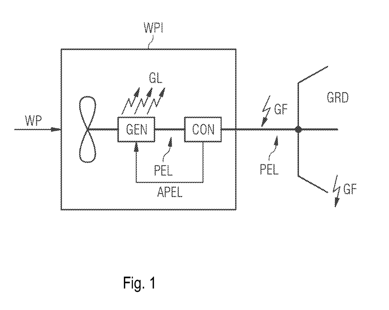
[0035]This FIGURE is only an example and does not limit the scope of embodiments of the invention.

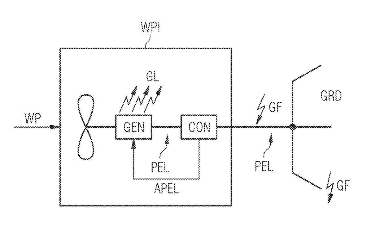
[0036]The wind power installation WPI comprises a generator GEN and a converter CON.

[0037]The generator GEN is operable to convert wind power WP into electrical power PEL. The electrical power PEL from the generator GEN is provided to the converter CON.

[0038]The converter CON is operable to adapt and to provide the electrical power PEL to an electrical grid GRD.

[0039]The converter CON is operable to comply with pre-determined grid code requirements during a grid fault GF, which might happen at the grid GRD.

[0040]According to embodiments of the invention an amount of electrical power APEL, which is present in the wind power installation during the grid fault GF, is fed back into the generator GEN.

[0041]The generator GEN is operable to convert the respective amount of electrical power APEL into a thermal loss GL in the generator GEN.

[0042]Although the present invention has been described ...


PUM


Abstract

A method to control a wind power installation is provided. The wind power installation includes a generator and a converter. The generator is configured to convert wind power into electrical power and to provide the electrical power from the generator to the converter. The converter is configured to adapt and to provide the electrical power to an electrical grid. The converter is operable to comply with pre-determined grid code requirements during a grid fault. An amount of electrical power, which is present in the wind power installation during the grid fault, is fed into the generator. The generator is operable to convert the respective amount of electrical power into a generator loss.

Description

CROSS-REFERENCE TO RELATED APPLICATIONS[0001]This application claims priority European application No. EP 15189362.5 having a filing date of Oct. 12, 2015, the entire contents of which are hereby incorporated by reference.FIELD OF TECHNOLOGY[0002]The following deals with a method to control a wind power installation. The wind power installation comprises a generator and a converter. The generator is operable to convert wind power into electrical power and to provide the electrical power from the generator to the converter. The converter is operable to adapt and to provide the electrical power to an electrical grid. The converter is operable to comply with pre-determined grid code requirements during a grid fault.BACKGROUND[0003]Wind power installations, like wind turbines or wind power plants, have to comply with given and specified grid codes, which are ruling the behavior of the wind power installations for given situations. These grid codes are specified in dependency of the capa...

Claims


Application Information

Patent Timeline
Patent Type & Authority Applications(United States)
IPC IPC(8): H02P9/10F03D7/02H02K7/18
CPCH02P9/10F03D7/0284H02K7/183F03D7/0272F03D7/0292H02J2300/28H02J3/381F03D7/0264F05B2260/903F05B2270/1071H02P2101/15H02J3/48H02J3/50H02J3/38Y02E10/72Y02E10/76
Inventor ANDERSEN, KURTEGEDAL, PERHJORT, THOMAS
Owner SIEMENS AG
Why Eureka
Try Eureka