Smart patio heater device

a heater device and smart technology, applied in the field of outdoor space heaters, can solve the problems of reducing and wasting a lot of heat on the top surface, and achieve the effect of increasing the efficiency of the heater

Inactive Publication Date: 2017-04-20
DOORANOISH SEYED MEHDI
View PDF6 Cites 8 Cited by
  • Summary
  • Abstract
  • Description
  • Claims
  • Application Information

AI Technical Summary

Benefits of technology

The patent is about a smart portable patio heating system. The system includes a device with a vertical chamber for holding a gas tank and a burning area for generating heat. The device also has thermoelectric generators for converting the heat into electric power. The electric power is stored in batteries for later use. The system also has a water pipe that circulates heated water to prevent overheating of the thermoelectric generators and to evenly distribute heat across the surface area of the patio heater. The system can also have electronic devices that use the stored battery power for additional benefits or functions. The device can also be set up to automatically shut off after a certain amount of use to increase efficiency.

Problems solved by technology

The use of patio heaters helps to extend the working hours of the day in cold seasons during which it becomes difficult to enjoy outdoor activities comfortably due to chilled weather conditions.
These typical patio heaters provide heat in all directions and thus a lot of heat is wasted from the top surface which reduces the efficiency of the heater.
Thus, a management of these many devices along with the monitoring of their power supply creates an additional burden for the party managers.
Arranging power supply for different electronic devices leads to laying of long wires from one area to another of the outdoor facility which in turn many a times results in user being tripped over these wires.
Further, there is a need for a patio heater which provides heating based on a detection of a presence of user around the device thereby saving a remarkable amount of fuel consumption and manual effort.

Method used


Image

  • Smart patio heater device
  • Smart patio heater device
  • Smart patio heater device

Examples


Embodiment Construction

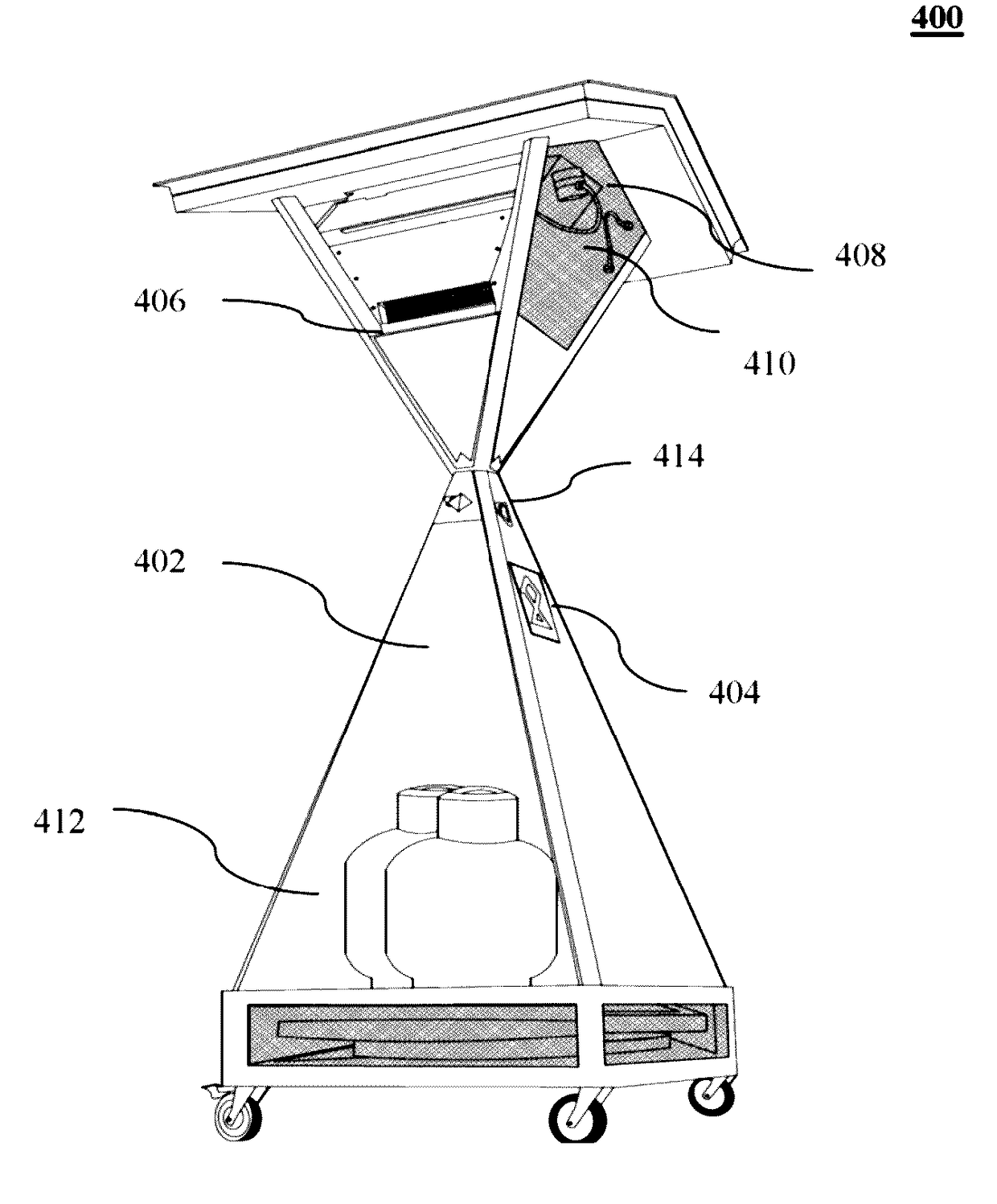
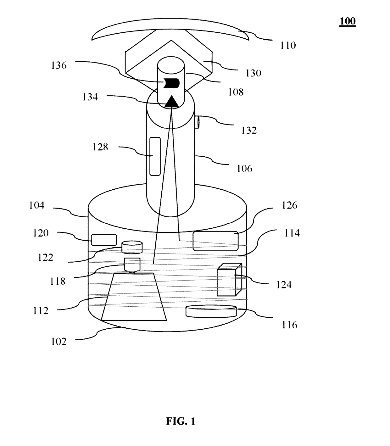
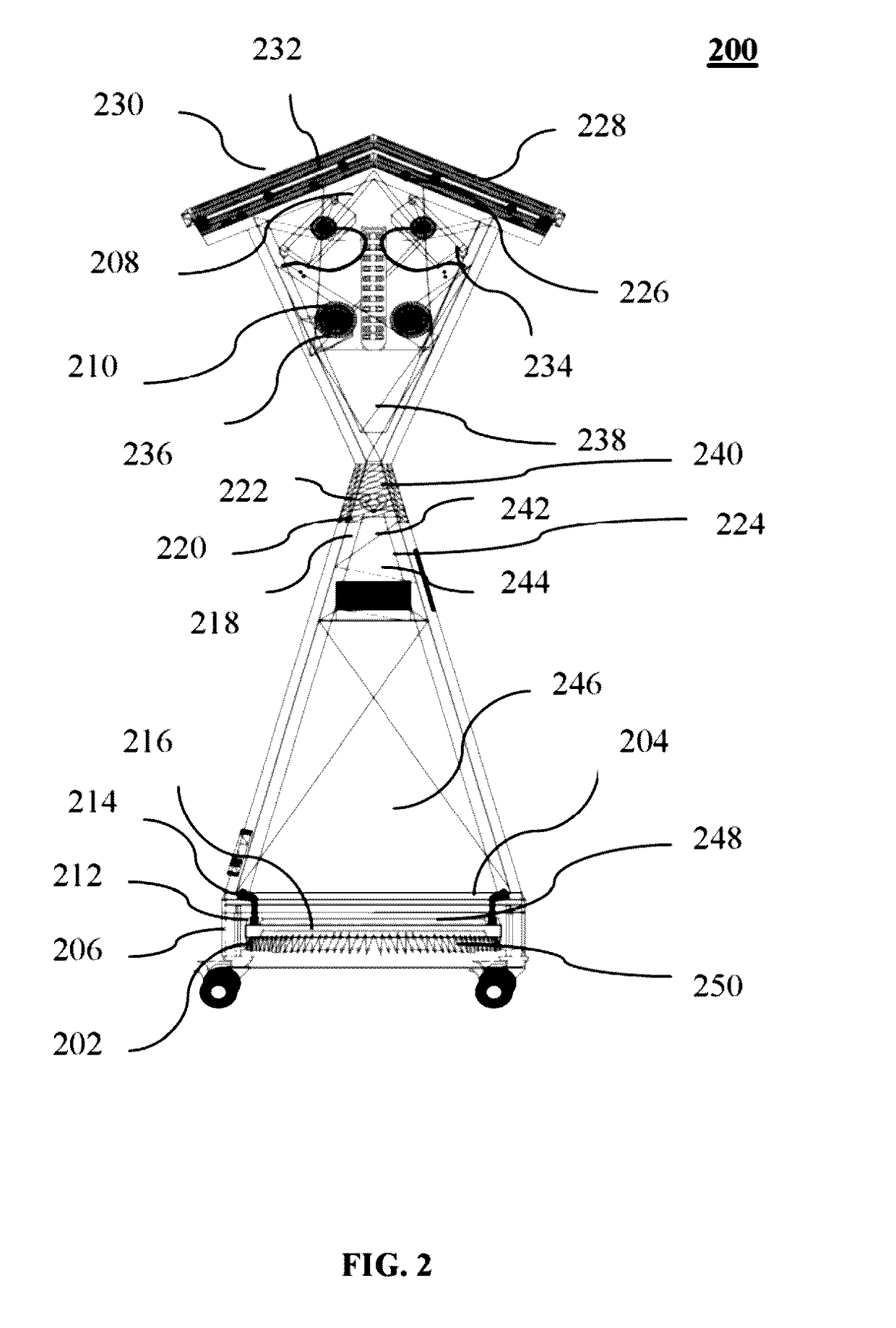
[0009]The primary object of the embodiments herein is to provide a patio heater or portable outdoor space heater which maximizes the heating efficiency by providing heat in a desired direction.

[0010]Another object of the embodiments herein is to provide a patio heater which makes use of the heat wasted from the top portion and converts the heat from top portion into useful electrical energy for driving several other electronic devices.

[0011]Yet another object of the embodiments herein is to provide a patio heater which provides heating only based on a detection of presence of a user presence around the device thereby saving a remarkable amount of fuel consumption and manual effort.

[0012]Yet another object of the embodiments herein is to provide a smart outdoor patio heater which houses several other electronic devices such as music system, food ordering kiosk, lighting system, etc., operated along with the patio heater.

[0013]Yet another object of the embodiments herein is to develop...


PUM


Abstract

The embodiments herein provide a smart patio heater device comprising a base having vertically extending chamber for receiving a gas from tank to supply gas to a gas burning area for generating heat which is dissipated in all directions or to a user desired area. The thermoelectric generators (TEG) are affixed over the burning area for generating electric power from the heat. The generated power is provided to a central processing system and stored in the batteries for later use. A water pipe connected between a water storage unit and TEG unit at is encircled around chamber and passed through the post. The water is circulated within the water pipe to absorb the excess heat generated around the TEG unit to prevent overheating. The electronic devices are provided to derive electrical power from the batteries for providing additional functions to the user.

Description

BACKGROUND[0001]Technical Field[0002]The embodiments herein are generally related to the field of outdoor space heaters. The embodiments herein are particularly related to portable heating apparatus. The embodiments herein are more particularly related to outdoor patio heaters for providing heat in all directions or in a specific area desired by the user.[0003]Description of the Related Art[0004]Traditionally outdoor patio heaters are commonly used for places such as restaurants and outdoor recreational facilities to provide warmth in preselected outdoor areas thereby making it much more comfortable for those who like to be outdoors. The use of patio heaters helps to extend the working hours of the day in cold seasons during which it becomes difficult to enjoy outdoor activities comfortably due to chilled weather conditions. Patio heaters typically comprise a base chamber that is sized to contain a fuel tank therein and a post connected to the base chamber projecting upward there fr...

Claims


Application Information

Patent Timeline
IPC IPC(8): F24C3/14H05K7/20F21S9/02H04W4/00F21S8/08G06F3/16G06Q50/12G06Q30/06H02J7/00H05B33/08H04W4/80H05B44/00
CPCF24C3/14H02J7/0013H05K7/20218F21S9/02H05B33/0845F21S8/08F21W2131/10G06F3/165G06Q50/12G06Q30/0641H04W4/008F21Y2115/10H05B33/0872F24C1/12F24C3/042H04W4/80H05B45/10H02J2310/22H02J7/0042F21V29/90F21V33/0092H02J7/00
Inventor DOORANDISH, SEYED MEHDI
Owner DOORANOISH SEYED MEHDI
Why Eureka
Try Eureka