System for measuring six degrees of freedom

a technology of freedom measurement and system, applied in the direction of direction/deviation determining electromagnetic system, instruments, reradiation, etc., can solve the problem that the absolute distance meter was too slow to accurately find the position of a moving targ

Inactive Publication Date: 2017-04-20
FARO TECH INC
View PDF2 Cites 39 Cited by
  • Summary
  • Abstract
  • Description
  • Claims
  • Application Information

AI Technical Summary

Problems solved by technology

Prior to the '446 patent, absolute distance meters were too slow to accurately find the position of a moving target.

Method used


Image

  • System for measuring six degrees of freedom
  • System for measuring six degrees of freedom
  • System for measuring six degrees of freedom

Examples


Embodiment Construction

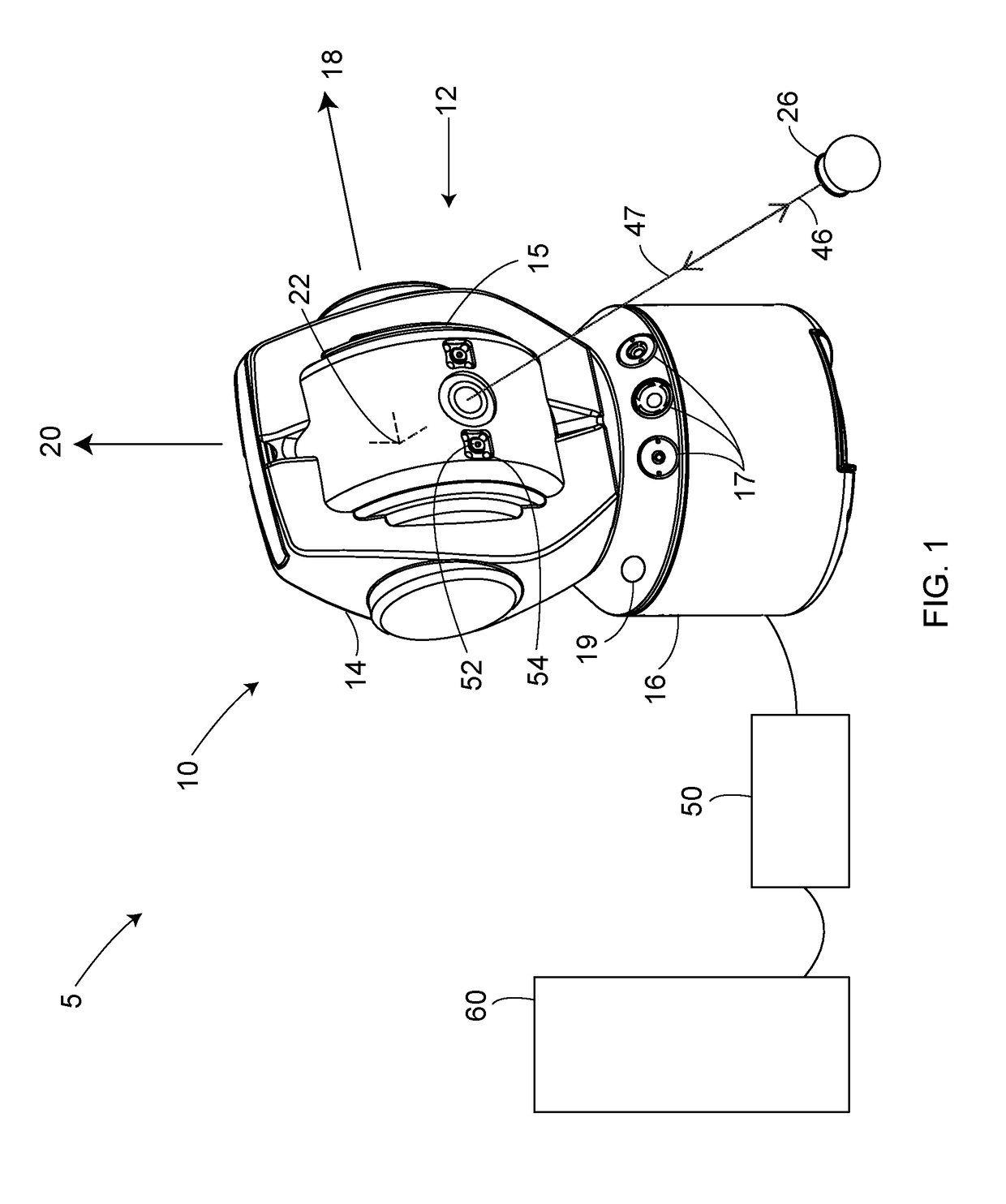
[0104]An exemplary laser tracker system 5 illustrated in FIG. 1 includes a laser tracker 10, a retroreflector target 26, an optional auxiliary unit processor 50, and an optional auxiliary computer 60. An exemplary gimbaled beam-steering mechanism 12 of laser tracker 10 comprises a zenith carriage 14 mounted on an azimuth base 16 and rotated about an azimuth axis 20. A payload 15 is mounted on the zenith carriage 14 and rotated about a zenith axis 18. Zenith axis 18 and azimuth axis 20 intersect orthogonally, internally to tracker 10, at gimbal point 22, which is typically the origin for distance measurements. A beam of light 46 virtually passes through the gimbal point 22 and is pointed orthogonal to zenith axis 18. In other words, beam of light 46 lies in a plane approximately perpendicular to the zenith axis 18 and that passes through the azimuth axis 20. Outgoing beam of light 46 is pointed in the desired direction by rotation of payload 15 about zenith axis 18 and by rotation of...


PUM


Abstract

A system that measures six degrees-of-freedom of a remote target, the system including a dimensional measuring device having a camera, the remote target including a retroreflector, at least three light markers, and a pitch-yaw sensor, the six degrees-of-freedom determined based at least in part on measured 3D coordinates of the retroreflector by the dimensional measuring device, on a captured image of the at least three light markers by the camera, and on readings of the pitch-yaw sensor.

Description

CROSS REFERENCE TO RELATED APPLICATIONS[0001]This application claims the benefit of U.S. patent application Ser. No. 15 / 194,914 filed on 28 Jun. 2016, which is a nonprovisional application of U.S. Provisional Patent Application No. 62 / 237,299 filed on Oct. 5, 2015 and U.S. Provisional Patent Application No. 62 / 186,447 filed on Jun. 30, 2015, the entire contents all of which are incorporated herein by reference in their entirety.BACKGROUND[0002]The present disclosure relates to a coordinate measuring device having the ability to determine three orientational degrees of freedom, and in particular to a coordinate measuring device cooperates with a device configured to measure three translational degrees of freedom, thereby enabling determination of the position and orientation of a rigid body in space.[0003]Some coordinate measurement devices have the ability to measure the three-dimensional (3D) coordinates of a point (the three translational degrees of freedom of the point) by sendin...

Claims


Application Information

Patent Timeline
Patent Type & Authority Applications(United States)
IPC IPC(8): G01P13/02G01S3/786G01S17/66
CPCG01P13/025G01S3/786G01S17/66G01B11/002G01S3/783G01S5/163
Inventor ATLAS, MIKHAILBROWN, LAWRENCE B.CHRISTINE, WILLIAM W.KIM, MAX K.O'NEILL, DANIEL J.SCHLOSS, JAMESXU, ZHIGUANG WILLAMBRIDGES, ROBERT E.
Owner FARO TECH INC
Why Eureka
Try Eureka