Micromirror device and projection device

a projection device and micromirror technology, applied in the field of micromirror devices and projection devices, can solve the problems of significant plastic deformation, electrical components, surfaces, etc., and achieve the effect of avoiding undesirable oscillations, avoiding distortion, and avoiding distortion

Active Publication Date: 2017-04-20
ROBERT BOSCH GMBH
View PDF4 Cites 4 Cited by
  • Summary
  • Abstract
  • Description
  • Claims
  • Application Information

AI Technical Summary

Benefits of technology

[0026]In one specific embodiment, the guiding device is designed to provide a rotational movement of the drive element out of the first plane in a predefined tolerance range. If a rotational mo...

Problems solved by technology

Due to the relatively large rotational mass of the drive of such a micromirror, the overall structure, or parts thereof, made up of a quasistatic mirror, a resonant mirror, mechanical fixing elements, magnets, electronic parts, including connecting surfaces, in particular adhesive surfaces, may be excited into undesirable oscillations.
Connecting parts made of plastic, in particular adhesive bonds, may have a significant plastic deformation in the event of such oscillations, whic...

Method used


Image

  • Micromirror device and projection device
  • Micromirror device and projection device
  • Micromirror device and projection device

Examples


Embodiment Construction

[0029]The present invention is explained in greater detail hereafter on the basis of the exemplary embodiments indicated in the schematic figures.

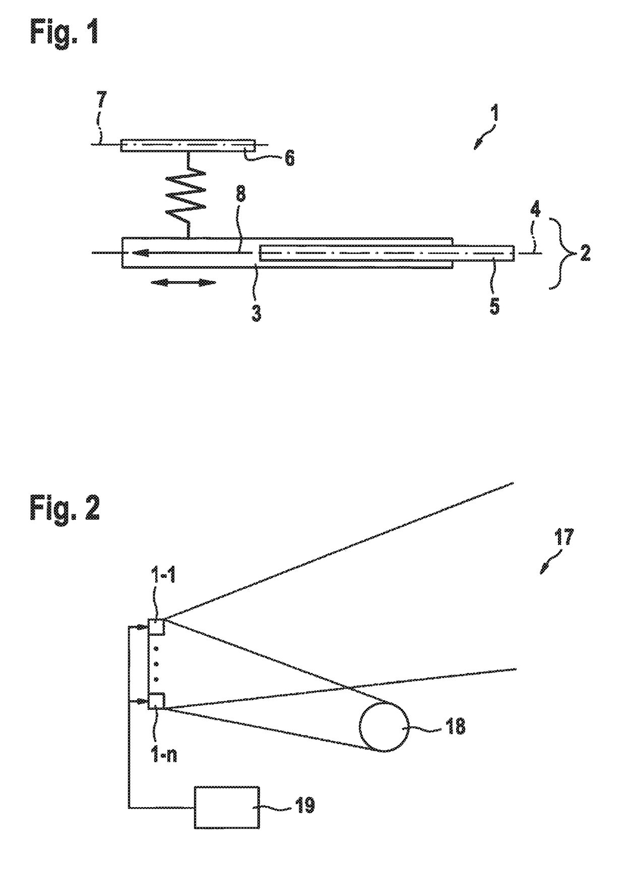
[0030]FIG. 1 shows a block diagram of one specific embodiment of a micromirror device according to the present invention.

[0031]FIG. 2 shows a block diagram of one specific embodiment of a projection device according to the present invention.

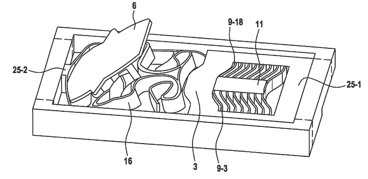
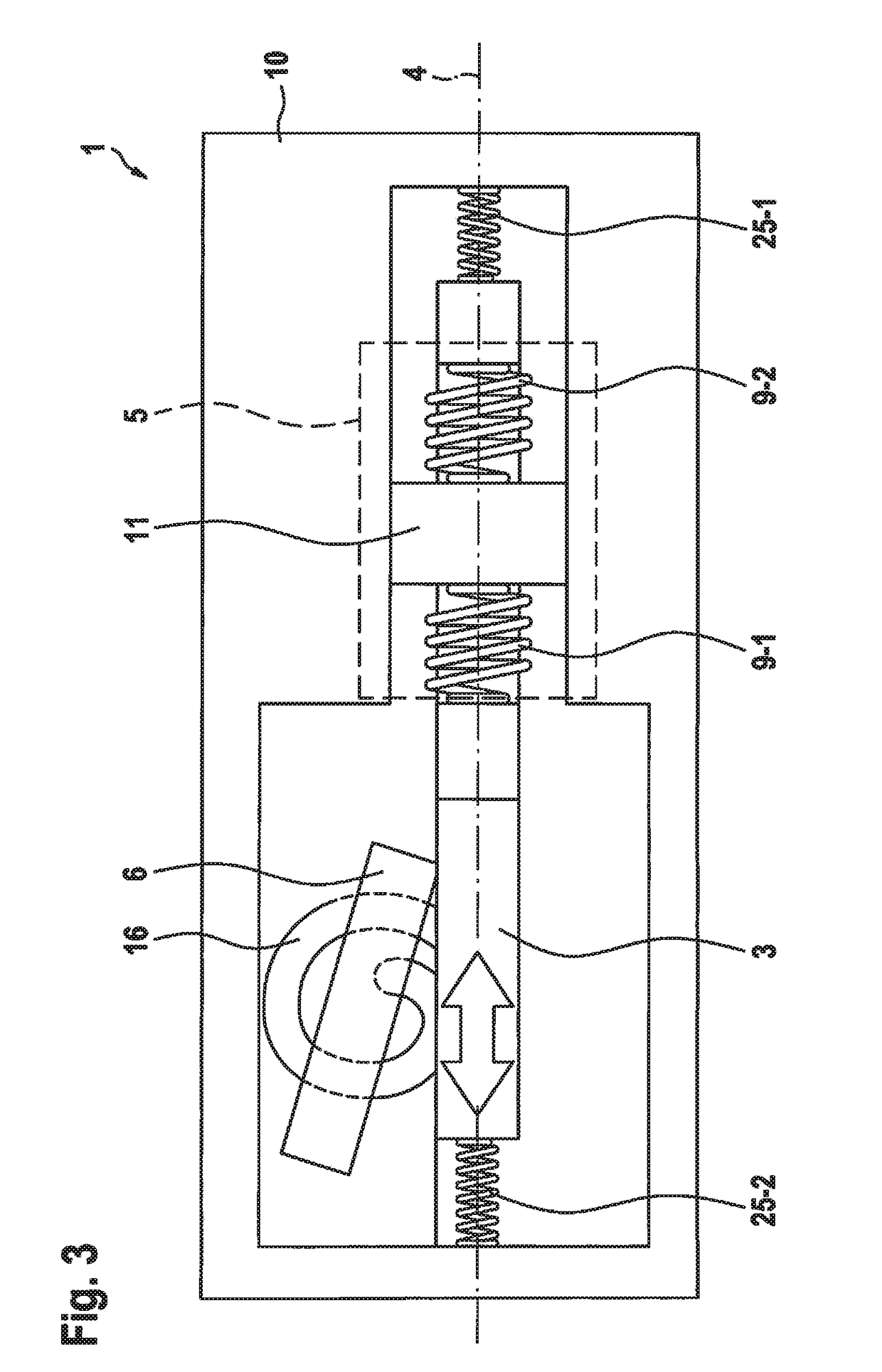
[0032]FIG. 3 shows a schematic view of one specific embodiment of a micromirror device according to the present invention.

[0033]FIG. 4 shows a schematic view of one specific embodiment of a micromirror device according to the present invention.

[0034]FIG. 5 shows a schematic view of one specific embodiment of a micromirror device according to the present invention.

[0035]FIG. 6 shows a schematic view of one specific embodiment of a micromirror device according to the present invention.

[0036]FIG. 7 shows a schematic view of one specific embodiment of a micromirror device according to the present invention....


PUM


Abstract

A micromirror device including a drive unit, which includes a movable drive element, which is situated in a first plane, and a guiding device, and a mirror, which is elastically coupled to the drive element and is situated in the idle position in a second plane, which is in parallel to the first plane, the guiding device being designed to guide a movement of the drive element on a straight line situated in the first plane. Furthermore, a corresponding projection device is described.

Description

FIELD[0001]The present invention relates to a micromirror device and a projection device including a micromirror device according to the present invention.BACKGROUND INFORMATION[0002]Micromirrors are presently used in a continuously increasing number of applications. These applications include, for example, projectors, scanners, or the like. The advantage of the micromirrors is that they occupy little space and may therefore be used very flexibly.[0003]Micromirrors are typically micro-electromechanical elements which are structured and manufactured, for example, with the aid of the conventional methods from semiconductor processing.[0004]Different methods may be used to implement the deflection of the mirrors in such a micromirror. For example, electrostatic drive methods, magnetic drive methods, piezoelectric drive methods, or the like may be used. Some drive methods only offer the option of tilting the mirror in one direction. Other drive methods also offer the option of tilting t...

Claims


Application Information

Patent Timeline
IPC IPC(8): G02B26/08B81B3/00G03B21/20
CPCG02B26/085G03B21/2066B81B2201/042B81B2203/058B81B3/0054G02B26/105B81B2203/051B81B2201/04
Inventor STRAUB, RAINERBAADER, JOHANNESDUELL, ANDREASNJIMONZIE, FREDERIC NJIKAMMUCHOW, JOERGGRUTZECK, HELMUT
Owner ROBERT BOSCH GMBH
Why Eureka
Try Eureka