Process to produce a workpiece surface on a rod-shaped workpiece

a technology of workpiece surface and rod-shaped workpiece, which is applied in the direction of manufacturing tools, other manufacturing equipment/tools, welding/soldering/cutting articles, etc., can solve the problems of insufficient roughness of workpiece surface, difficult production of tool surface, and groove inner surface of rod-shaped workpiece, etc., and achieves relatively large volume of material to be removed.

Active Publication Date: 2017-04-27
FRITZ STUDER AG
View PDF10 Cites 5 Cited by
  • Summary
  • Abstract
  • Description
  • Claims
  • Application Information

AI Technical Summary

Benefits of technology

[0036]It is also possible to use the process described above only for smoothing operations. A workpiece surface or a groove inner surface can be produced by any premachining process to leave an oversize, and the inventive process can be used for subsequent prod...

Problems solved by technology

Producing tool surfaces, for example groove inner surfaces, on a rod-shaped workpiece using a pulsed laser is difficult.
However, in some cases the workpiece surfaces that are produced, which have laser beam pulses impinge...

Method used


Image

  • Process to produce a workpiece surface on a rod-shaped workpiece
  • Process to produce a workpiece surface on a rod-shaped workpiece
  • Process to produce a workpiece surface on a rod-shaped workpiece

Examples


Embodiment Construction

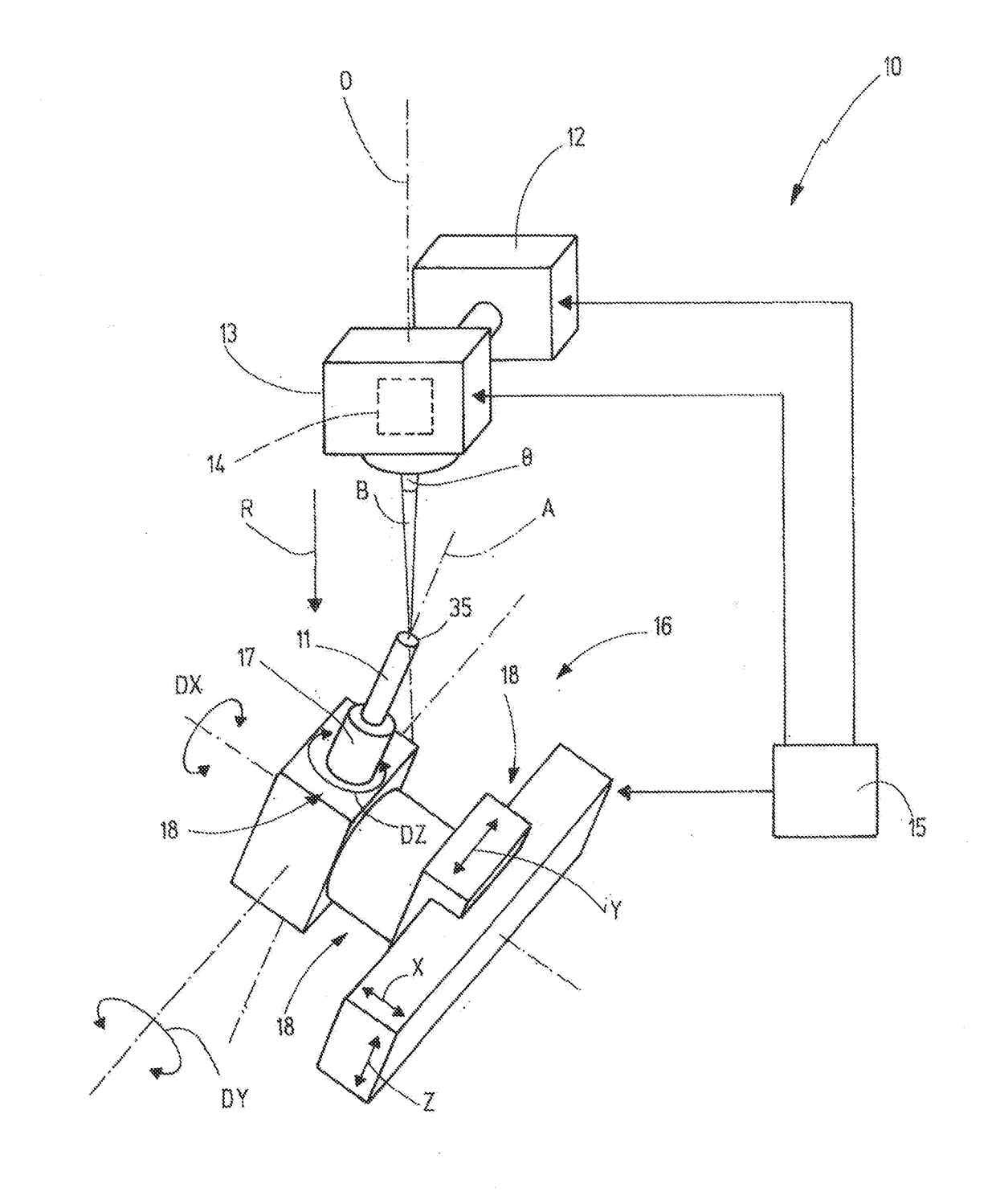
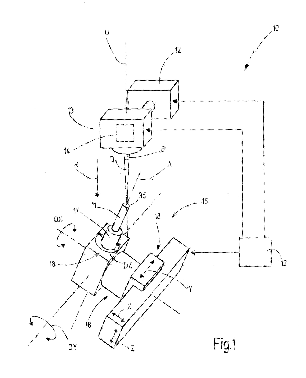
[0044]FIG. 1 schematically illustrates a machining machine 10, which is designed to perform an inventive process to machine a rod-shaped workpiece 11. The unmachined workpiece 11 has a cylindrical shape; according to the example it is circular cylindrical. Machining the workpiece 11 with machining machine 10 produces a rotary tool that rotates about the longitudinal axis A of the workpiece 11 or the tool produced from it.

[0045]The machining machine 10 has a pulsed laser 12 that produces a pulsed laser beam, that is laser beam pulses B. The pulsed laser beam is sent from laser 12 to a laser head 13. The laser head 13 is designed to emit the laser beam pulses B in a specified direction with respect to its optical axis O, and focus them in a machining area. While the workpiece 11 is being machined, the currently machined surface of the workpiece 11, that is the material removal site or the material removal surface, is located within the machining area.

[0046]The laser head 13 can have f...


PUM

PropertyMeasurementUnit
Areaaaaaaaaaaa
Depthaaaaaaaaaa
Distanceaaaaaaaaaa

Abstract

A process to produce a workpiece surface or a groove inner surface on a rod-shaped, especially cylindrical workpiece. From the workpiece, a rotary tool is supposed to be produced. The material removal is done using laser beam pulses, which are directed through a deflection device onto points of incidence within a pulse area with a specified outside contour on the workpiece. Multiple machine axis drives position the workpiece and the deflection device relative to one another so that the pulse area is oriented essentially at right angles to the emission direction of the laser beam pulses and at right angles to the section of the tool surface that has already been produced and that borders the pulse area. While the material is being removed, the at least one machine axis drive moves the pulse area relative to the workpiece along a specified path of motion while maintaining the orientation.

Description

CROSS-REFERENCE TO RELATED APPLICATION[0001]This is a continuation-in-part application of pending international application PCT / EP2015 / 062898 filed Jun. 10, 2015 and claiming the priority of German Application No. 10 2014 109 613.4 filed Jul. 9, 2014. The aforesaid pending international application PCT / EP2015 / 062898 and German Application No. 10 2014 109 613.4 are both incorporated herein by reference as though fully set forth.BACKGROUND OF THE INVENTION[0002]The invention relates to a process to produce a workpiece surface using a machining machine with a laser that produces laser beam pulses. The machining machine additionally has a laser head that directs the laser beam pulses of the laser onto the workpiece. A machine drive unit with at least one machine axis drive orients and moves, through the respective associated machine axis drive, the workpiece and the laser head relative to one another in at least one translational and / or rotational degree of freedom.[0003]Such a machinin...

Claims


Application Information

Patent Timeline
IPC IPC(8): B23K26/364B23K26/40B23K26/082B23K26/0622B23K26/08
CPCB23K26/364B23K26/0622B23K26/0823B23K2203/18B23K26/082B23K26/40B23K2201/20B23K26/0861B23K2101/20B23K2103/18
Inventor PLUSS, CHRISTOPHFREI, BRUNODOLD, CLAUSWARHANEK, MAXIMILIANWALTER, CHRISTIAN
Owner FRITZ STUDER AG
Why Eureka
Try Eureka