Electronic circuit for a blind-spot monitoring display

a technology of electronic circuit and blind-spot monitoring display, which is applied in the direction of electroluminescent light sources, electric lighting sources, transportation and packaging, etc., can solve the problems of limited space in the area of blind-spot display, module cannot be mounted to any extent at all or only at a single position,

Inactive Publication Date: 2017-04-27
SMR PATENTS S A R L
View PDF9 Cites 5 Cited by
  • Summary
  • Abstract
  • Description
  • Claims
  • Application Information

AI Technical Summary

Benefits of technology

[0023]The above-described electronic circuit can be used for the most varied applications in a driver-assistance system, for example for the blind-spot monitoring display as described above, but also for other applications. For example, the circuit can be used for an indicator in order to thus signal the intention of the driver soon he wanting to charge the lane to vehicles driving alongside or behind the driver who are located outside of the radiation angle of the front or rear indicator. The advantage of such a system is also that the control unit need not be installed together with the electronic circuit in the vehicle, but can be located at other positions, say, at any position in the vehicle where there is sufficient space. The electronic circuit can be mounted at positions suitable for the driver, such as in the exterior mirror, for example. Thus not the entire control apparatus need to be designed compact, but it is sufficient if merely the electronic circuit is designed compact.
[0024]According to an embodiment of the driver-assistance system, the state of the control device is based on a blind-spot monitoring. The advantage of this is that the con

Problems solved by technology

The space available in the vehicle for accommodating an electronic circuit for the blind-spot monitoring display is limited, in particular in the exterior mirror of the vehicle, predetermined by the construction.
The size of the available space in the area of the blind-spot display is limited.
As a result, the module cannot be mounted to any extent at

Method used


Image

  • Electronic circuit for a blind-spot monitoring display
  • Electronic circuit for a blind-spot monitoring display
  • Electronic circuit for a blind-spot monitoring display

Examples


Embodiment Construction

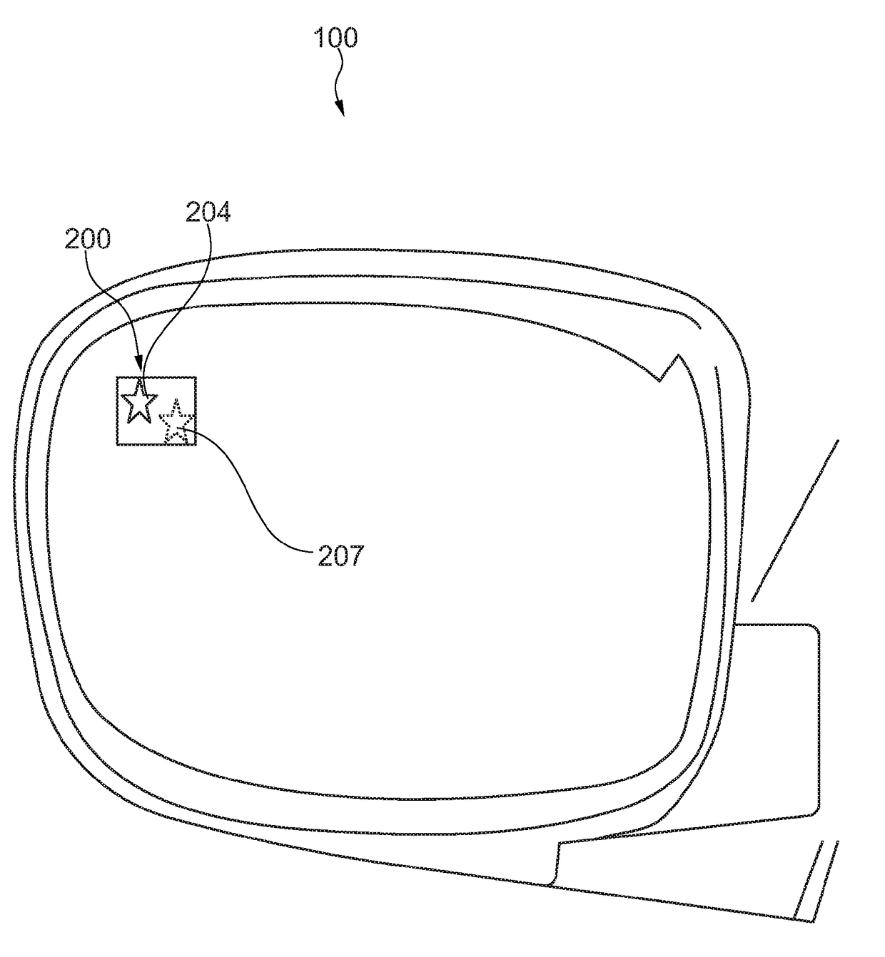
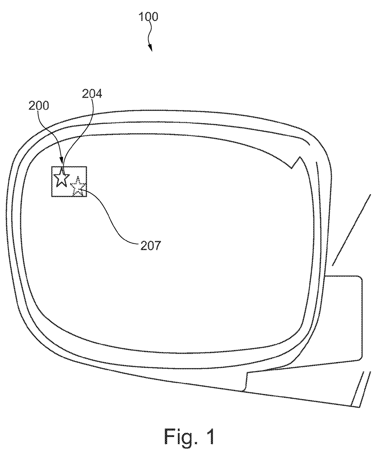
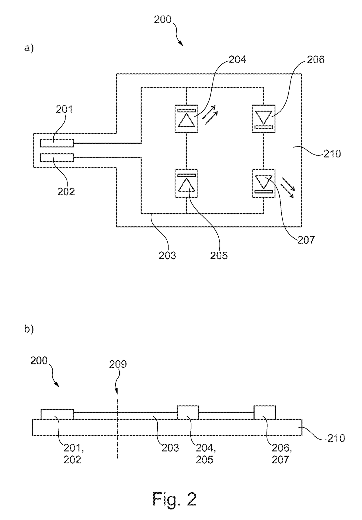
[0039]FIG. 1 shows a schematic representation of a vehicle exterior mirror 100 having an integrated electronic circuit 200 for a blind-spot monitoring display according to an embodiment. The electronic circuit 200 comprises two light sources 204, 207, represented by two stars which can be switched on or off alternately, for example by a control apparatus (not shown), which can be placed in the boot of the vehicle, as described in more detail in FIG. 4. The two light sources can be realized by light-emitting diodes (LEDs). The electronic circuit 200 is described in more detail below in respect of FIGS. 2a) and 2b). It comprises a circuit connection having two connectors, i.e. connectors to which a cable can be attached, as well as circuit means which make possible an alternate switching-on of the first light source 204 and the second light source 207. This means that either the first light source 204 lights up, for example in a first colour, e.g. green, or the second light source 207...


PUM


Abstract

The invention relates to an electronic circuit for a blind-spot monitoring display, having a circuit carrier; a first light source and a second light source mounted to the circuit carrier. A circuit connection is mounted to the circuit carrier, which circuit connection is coupled to the first light source and the second light source. The electronic circuit comprises circuit means which are designed, on the basis of a polarity of a voltage applied to the circuit connection to supply current either to the first light source or to the second light source.

Description

CROSS-REFERENCE TO RELATED APPLICATIONS[0001]This application is the National Phase of International Application PCT / IB2015 / 053278 filed May 5, 2015 which designated the U.S. and that International Application was published on Nov. 19, 2015 as International Publication Number WO 2015 / 173692A1. PCT / IB2015 / 053278 claims priority to European Patent Application No. 14167967.0, filed May 12, 2014. Thus, the subject nonprovisional application claims priority to European Patent Application No. 14167967.0, filed May 12, 2014. The disclosures of both applications are incorporated herein by reference in their entirety.BACKGROUND OF THE INVENTION[0002]The present invention relates to an electronic circuit for an illumination device in a review device for a motor vehicle, a driver-assistance system comprising such a circuit, a rear-view device having such an electronic circuit, a method for producing such a circuit and a motor vehicle having such a rear-view device and / or having such an electro...

Claims


Application Information

Patent Timeline
IPC IPC(8): B60R1/12B60R1/06H05B33/08B60Q9/00H05B44/00
CPCB60R1/12B60Q9/008B60R1/06B60R2001/1215H05B33/0872B60Q2400/00H05B33/089B60R1/1207B60Q1/2665H05B45/00H05B45/50H05B45/30
Inventor FRITZ, DANIEL
Owner SMR PATENTS S A R L
Why Eureka
Try Eureka