Vehicle Side Wing Anti-collision System

Active Publication Date: 2017-04-27
TSANG CHEUNG
View PDF0 Cites 2 Cited by
  • Summary
  • Abstract
  • Description
  • Claims
  • Application Information

AI Technical Summary

Benefits of technology

The present invention provides a vehicle side wing anti-collision system that uses a telescopic assembly and a collision panel to form protection layers on two sides of the vehicle. This system effectively prevents the vehicle side body from being deformed by a collision, protecting the safety of people inside the vehicle and improving the anti-collision performance of the vehicle side body.

Problems solved by technology

Following the development of vehicles and the increase of their quantity, traffic accidents are also on the rise and seriously threaten human safety.
According to the annual statistics reports on road traffic accidents of China, side collision accidents account for a large portion of traffic accidents in China and cause very high human casualties.
Compared to vehicle head-on collision, vehicle side face is vulnerable to deformation when it is subjected to a collision, thereby directly injuring people in the vehicle.

Method used


Image

  • Vehicle Side Wing Anti-collision System
  • Vehicle Side Wing Anti-collision System
  • Vehicle Side Wing Anti-collision System

Examples


embodiment 1

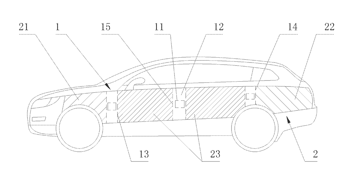
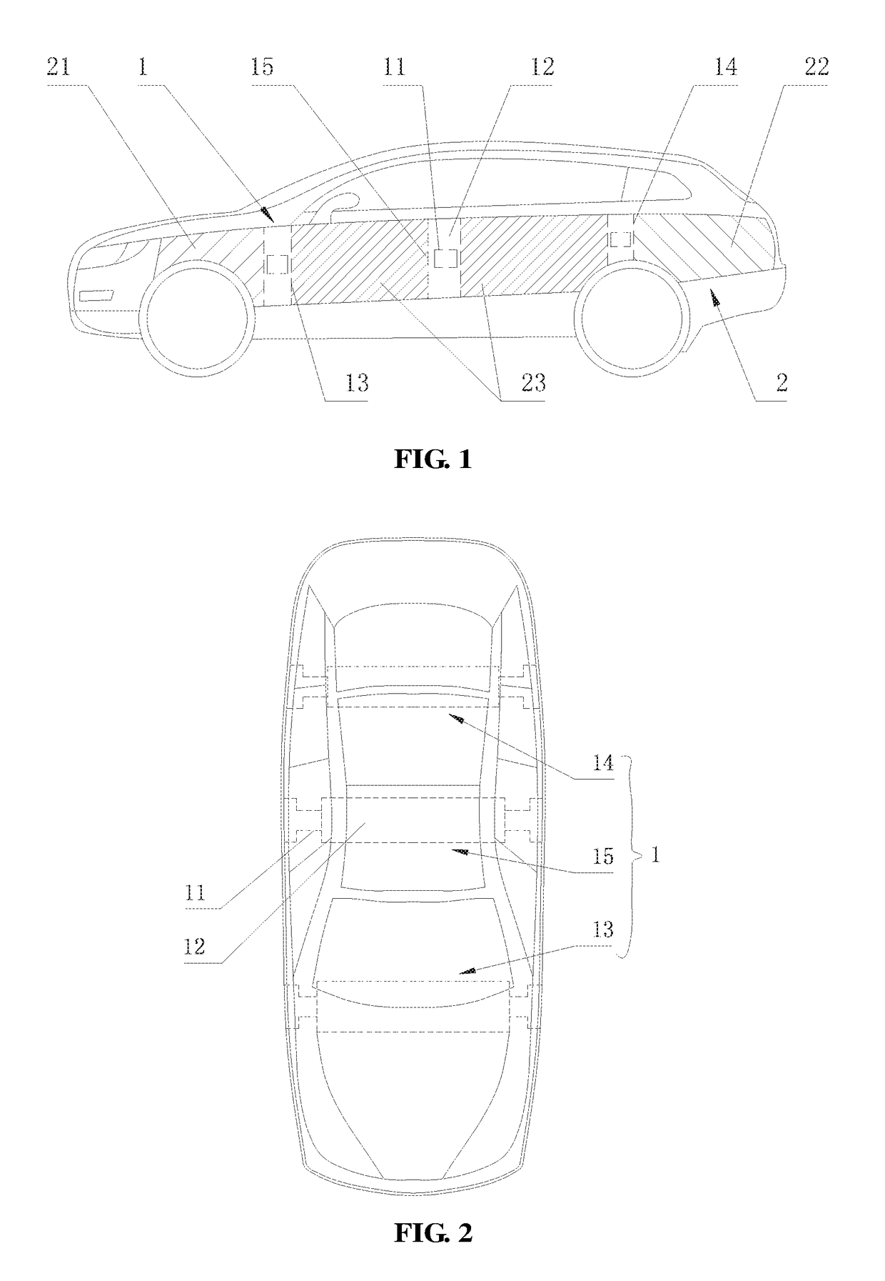
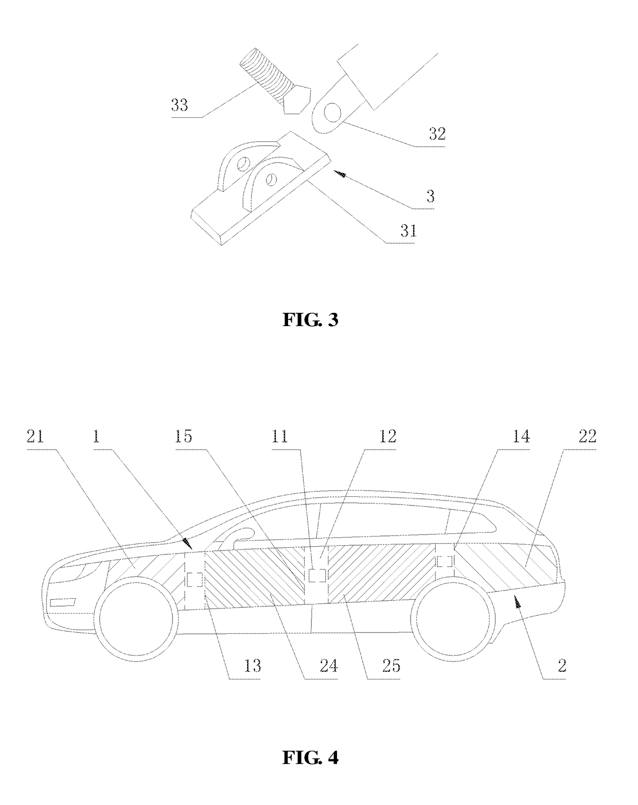
[0050]As shown in FIG. 1-FIG. 3, FIG. 7 and FIG. 8, this embodiment provides a vehicle side wing anti-collision system. FIG. 1 and FIG. 2 show an operating box-type telescopic assembly. FIG. 1 is a front view of a vehicle side wing anti-collision system provided by this embodiment. The section lines therein are not for expressing section lines but for more clearly indicating front aux wing, rear aux wing, main wing and other structures. FIG. 2 is a top view of FIG. 1 and does not show the collision panel due to a different viewing angle. FIG. 3 is perspective view of a slipknot holder in this embodiment. FIG. 7 is a perspective view of a vehicle side wing anti-collision system with a bearing frame type telescopic assembly, and does not show a collision panel. FIG. 8 is a schematic view of a bearing frame. The term “bearing frame” herein means that the frame is able to bear external mechanical force, such as pressing or pulling force.

[0051]As shown in FIG. 1, FIG. 2 and FIG. 7, a veh...

embodiment 2

[0104]Embodiment 2 provides a vehicle side wing anti-collision system. This embodiment is another technical solution improving the door outer panel, main wing and their connective relations on the basis of Embodiment 1. Other technical features disclosed by Embodiment 1 except the door outer panel, main wing and their connective relations are also applicable to this embodiment, and will not be described again.

[0105]FIG. 4 is a front view of a vehicle side wing anti-collision system provided by this embodiment. The section lines in the diagram are not for expressing section lines but for more clearly indicating front aux wing, rear aux wing, front main wing, rear main wing and other structures.

[0106]As shown in FIG. 4, the door outer panel in this embodiment comprises a front door outer panel and a rear door outer panel, the main wing 23 comprises a front main wing 24 and a rear main wing 25, in other words, it applies to a vehicle with four doors; the third telescopic mechanism 15 i...


PUM


Abstract

Disclosed is a vehicle side wing anti-collision system, including a telescopic assembly fixed on a vehicle frame; and a collision panel located in a groove of a vehicle side body and provided correspondingly to the telescopic assembly. The groove is provided with a connection hole and the telescopic assembly is extended out of the connection hole towards two sides in a transverse direction of the vehicle to drive the collision panel to extend out of the groove till protruding from the vehicle side body when the collision panel is subjected to a collision. Through the telescopic assembly and the collision panel, protection layers are formed on two sides of the vehicle, and thus the anti-collision ability of the vehicle side wing is enhanced.

Description

TECHNICAL FIELD OF THE INVENTION[0001]The present invention relates to vehicle field, and more particularly, to a vehicle side wing anti-collision system.BACKGROUND OF THE INVENTION[0002]Cars and large buses are common modern means of transport. Following the development of vehicles and the increase of their quantity, traffic accidents are also on the rise and seriously threaten human safety. According to the annual statistics reports on road traffic accidents of China, side collision accidents account for a large portion of traffic accidents in China and cause very high human casualties. Compared to vehicle head-on collision, vehicle side face is vulnerable to deformation when it is subjected to a collision, thereby directly injuring people in the vehicle.[0003]Therefore, a new vehicle side wing anti-collision system is in urgent need to address the foregoing problem.SUMMARY OF THE INVENTION[0004]The object of the present invention is to provide a vehicle side wing anti-collision s...

Claims


Application Information

Patent Timeline
IPC IPC(8): B60R19/40B60R19/28B60R19/42
CPCB60R19/40B60R19/42B60Y2400/406B60Y2400/408B60Y2400/405B60R19/28B60R19/023
Inventor TSANG, CHEUNG
Owner TSANG CHEUNG
Why Eureka
Try Eureka