
PRODUCTION METHOD FOR Fe-Ni BASED HEAT-RESISTANT SUPERALLOY

a production method and superalloy technology, applied in the field of fe — ni based heat-resistant superalloy production, can solve the problems of agg, abnormal grain growth, and rapid coarsening of grains, and achieve the effect of enhancing heat-resistant superalloy

Active Publication Date: 2017-04-27
HITACHI METALS LTD
View PDF1 Cites 4 Cited by
  • Summary
  • Abstract
  • Description
  • Claims
  • Application Information

AI Technical Summary

Benefits of technology

The patent aims to improve the quality of Fe-Ni based heat-resistant superalloys by avoiding the formation of a specific phase called AGG and creating a uniform and fine crystal grain structure. This improvement can make materials used in applications such as jet engines and gas turbines more reliable, especially in terms of fatigue resistance.

Problems solved by technology

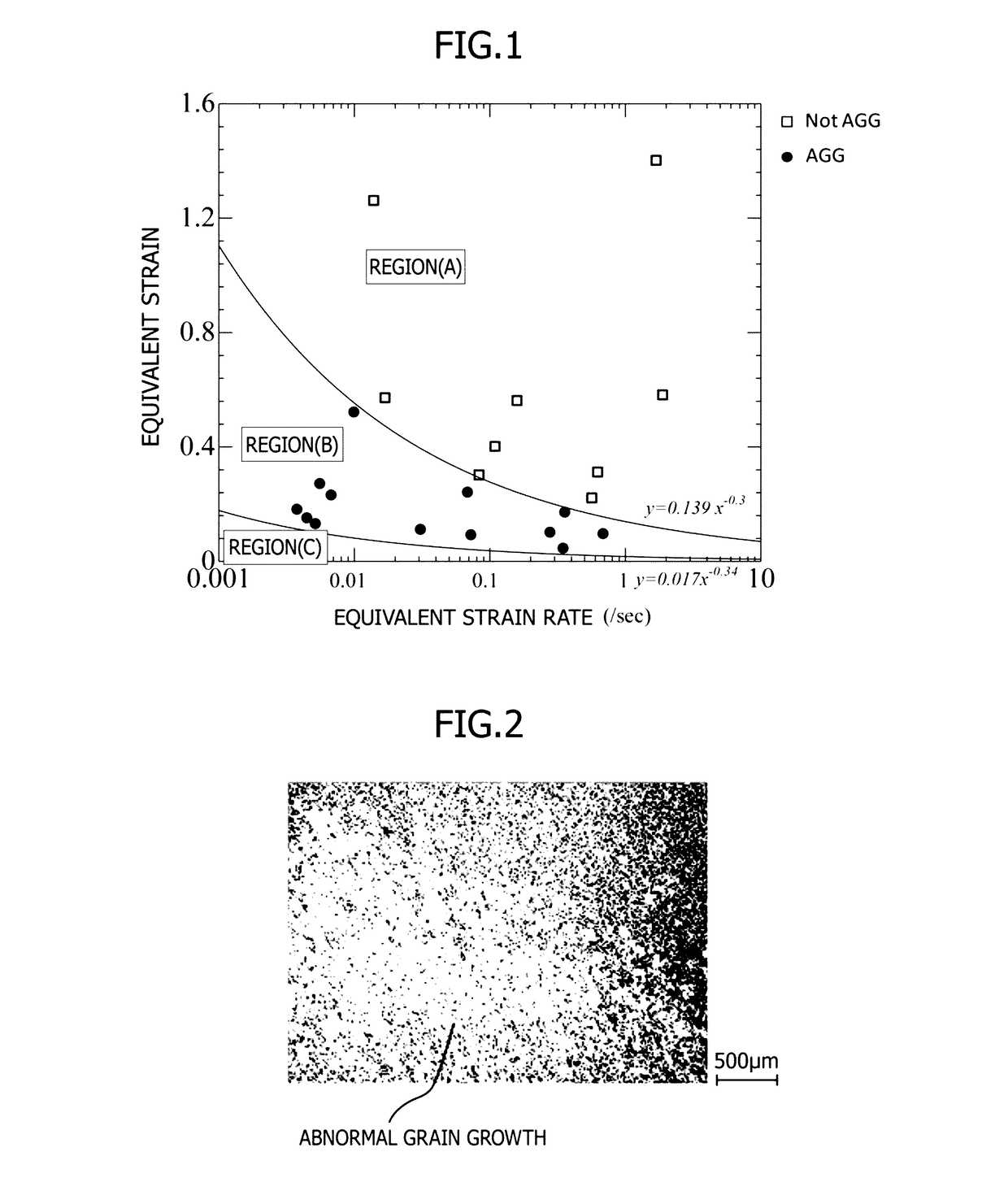
However, when carrying out hot working under low strain conditions by, for example, closed die forging or ring rolling, abnormal grain growth (hereinafter referred to as AGG) may occur and grains are rapidly coarsened beyond the pinning of the delta phase during the hot working, cooling after the hot working, or solution treatment after the hot working.
When such AGG occurs as shown in FIG. 2, a uniform fine structure is broken, and therefore the fatigue characteristic deteriorates.

Method used


Image

  • PRODUCTION METHOD FOR Fe-Ni BASED HEAT-RESISTANT SUPERALLOY
  • PRODUCTION METHOD FOR Fe-Ni BASED HEAT-RESISTANT SUPERALLOY

Examples


example 1

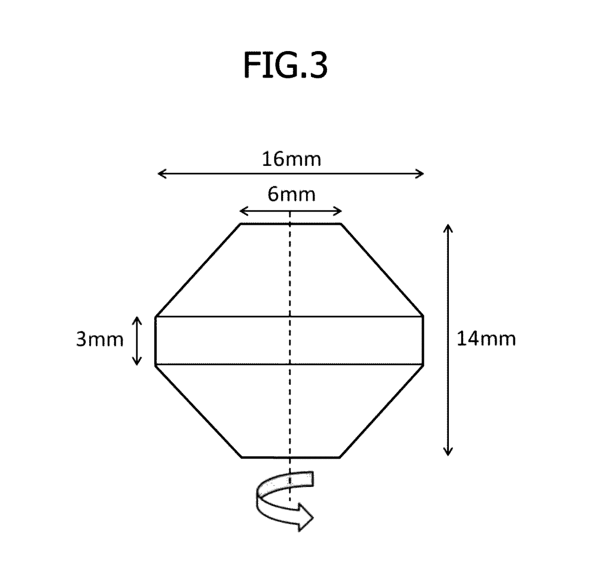
[0037]A billet having a chemical composition shown in Table 1 which corresponded to that of an Fe—Ni based heat-resistant superalloy (Alloy 718) was used and was subjected to upset forging in a temperature range of 950 to 1000° C., and then it was subjected to ring rolling in a temperature range of 950 to 1000° C. Next, the hot alloy described above was held at 980° C. for 1 hour in order to remove strain remaining in the alloy, and then it was cooled down to room temperature by air so as to prepare a small compression test piece shown in FIG. 3 and subject it to a hot working test. This small compression test piece was used as a sample material and subjected to the hot working test for investigating factors affecting the occurrence of AGG. The sample material had a crystal grain size of 10 in terms of an average crystal grain size number defined in ASTM-E112.

TABLE 1C0.023Si0.07Mn0.11P0.004S0.0002Ni54.9Cr17.97Mo2.98Co0.17Cu0.04Al0.48Ti0.95Nb + Ta5.44B0.0029BalanceFe and unavoidable ...

example 2

[0043]An 800 kg amount of material for hot working which comprises an Fe—Ni based heat-resistant superalloy (718 alloy) having the chemical composition shown in Table 1 was used and subjected to hot forging. The hot working material was subjected to hot forging in a temperature range of 980 to 1000° C. so that the effective strain satisfies the relation of the following equation in the entirety of the hot working material.

[0044]After the hot forging, the material was subjected to pre-heating and solution treatment for the six different conditions of (a) to (0 shown in Table 3 for the purpose of inhibiting the growth of grains during the solution treatment as much as possible, and then it was subjected to the first aging treatment at 718° C. for 8 hours and the second aging treatment at 621° C. for 8 hours.

(effective strain)≧0.139×(effective strain rate( / sec))−0.30   [Equation. 5]

TABLE 3Pre-heatingSolution treatmentRemarks(a)—982° C. × 1 hrPresent inventionAir cooling(ordinary soluti...


PUM

PropertyMeasurementUnit
Temperatureaaaaaaaaaa

Abstract

A production method for an Fe—Ni based heat-resistant superalloy inhibits abnormal grain growth and yields a fine crystal grain structure having an ASTM crystal grain size number of 9 or greater. The production method comprises at least a hot working step in which a material having a prescribed composition is subjected to hot working, wherein the hot working step includes at least a step in which the above material of 930 to 1010° C. is subjected to hot working so that the relation of (effective strain)≧0.139×(effective strain rate( / sec))−0.30 is satisfied in the entirety of the above material.

Description

TECHNICAL FIELD[0001]The present invention relates to a production method for an Fe—Ni based heat-resistant superalloy.BACKGROUND ART[0002]Alloy 718, which is an Fe—Ni based heat-resistant superalloy used in gas turbine parts for aircraft and power generation, has been widely used for its excellent mechanical properties. In particular, a high fatigue strength is required for large rotating parts in jet engines and gas turbines. Accordingly, Alloy 718 used for such parts is required to have a further enhanced fatigue strength by evenly micronizing grains. For evenly micronizing grains, a billet is often prepared from an ingot of Alloy 718 and then subjected to hot working in a temperature range of 930 to 1010° C. by making use of the pinning effect of the delta phase to form a fine recrystallized structure, and the billet is then subjected to solution treatment (solid solution heat treatment) and aging, or directly to aging.[0003]However, when carrying out hot working under low strai...

Claims


Application Information

Patent Timeline
IPC IPC(8): C22F1/10C22C19/05
CPCC22C19/056C22F1/10
Inventor AOKI, CHUYAOHNO, TAKEHIRO
Owner HITACHI METALS LTD
Learn More