Ducted fuel injection with ignition assist

a technology of ducted fuel and assist, which is applied in the direction of electric ignition installation, machines/engines, mechanical equipment, etc., can solve the problems of increasing the cost of initial equipment cost and subsequent maintenance of the combustion system, increasing the ignition delay of the mixture, and increasing the ignition delay of the fuel/charge-gas mixture. , to achieve the effect of facilitating the ignition of the fuel/charge-gas mixture, and increasing the ignition delay of the mixtur

Active Publication Date: 2017-04-27
NAT TECH & ENG SOLUTIONS OF SANDIA LLC
View PDF22 Cites 15 Cited by
  • Summary
  • Abstract
  • Description
  • Claims
  • Application Information

AI Technical Summary

Benefits of technology

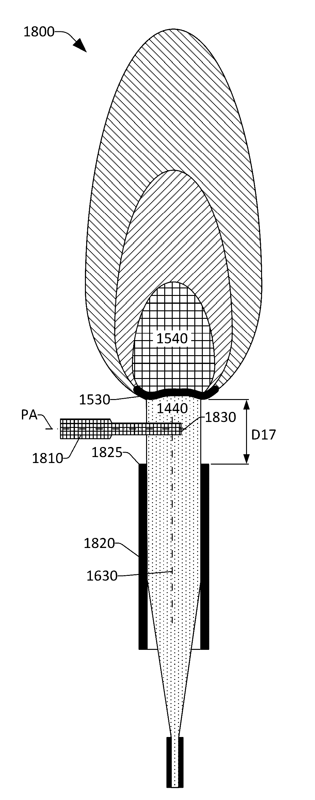
[0013]During operation of the engine, a temperature inside the bore of the duct may be less than an ambient temperature inside the combustion chamber such that the ignition delay of the mixture is increased, and mixing of the fuel and charge-gas prior to autoignition is further improved compared with direct injection of the fuel into the combustion chamber.
[0014]Operation of an engine utilizing the various embodiments presented herein may cause the ignition delay of the fuel / charge-gas mixture to increase. To facilitate ignition of the fuel / charge-gas mixture without excessive ignition delay, one or more ignition assist components can be utilized to ignite the fuel / charge-gas mixture. An ignition assist component can be a glow plug, a plasma torch, a laser emitting a focused laser beam, etc. Further, an ignition assist component can be fabricated with a layer of catalytic material located thereon, wherein the ignition assist component can be located with respect to the emission of the fuel / charge-gas mixture from a duct (e.g., in a flow path of the fuel / charge-gas mixture), wherein reaction of the fuel / charge-gas mixture facilitated by the catalytic material promotes ignition of the fuel / charge-gas mixture.

Problems solved by technology

While such “direct injection” engines represent an improvement in engine technology over past designs (e.g., carburetors) with regard to increased engine efficiency and reduced emissions, direct injection engines can produce relatively high levels of certain undesired emissions.
Currently, soot is removed from the exhaust of diesel engines by large and expensive particulate filters in the exhaust system.
These after-treatment systems have to be maintained to enable continued and effective reduction of soot / particulates and other undesired emissions, and accordingly add further cost to a combustion system both in terms of initial equipment cost and subsequent maintenance.

Method used


Image

  • Ducted fuel injection with ignition assist
  • Ducted fuel injection with ignition assist
  • Ducted fuel injection with ignition assist

Examples


Embodiment Construction

[0002]This invention was developed under contract DE-AC04-94AL85000 between Sandia Corporation and the U.S. Department of Energy. The U.S. Government has certain rights in this invention.

BACKGROUND

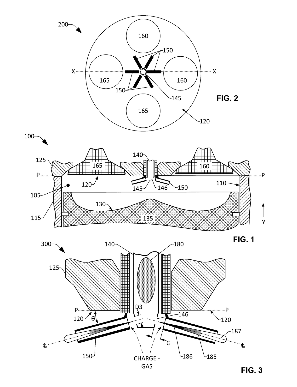
[0003]Many modern engines are designed such that each combustion cylinder of the engine includes a dedicated fuel injector configured to inject fuel directly into a combustion chamber. While such “direct injection” engines represent an improvement in engine technology over past designs (e.g., carburetors) with regard to increased engine efficiency and reduced emissions, direct injection engines can produce relatively high levels of certain undesired emissions.

[0004]Engine emissions can include soot, which results from combustion of a fuel-rich and oxygen-lean fuel mixture. Soot comprises small carbon particles created by the fuel-rich regions of diffusion flames commonly created in a combustion chamber of an engine which may be operating at medium to high load. Soot is an environmental haz...


PUM


Abstract

Various technologies presented herein relate to enhancing mixing inside a combustion chamber to form one or more locally premixed mixtures comprising fuel and charge-gas to enable minimal, or no, generation of soot and/or other undesired emissions during ignition and subsequent combustion of the locally premixed mixtures. To enable sufficient mixing of the fuel and charge-gas, a jet of fuel can be directed to pass through a bore of a duct causing charge-gas to be drawn into the bore creating turbulence to mix the fuel and the drawn charge-gas. The duct can be located proximate to an opening in a tip of a fuel injector. An ignition assist component can be located downstream of the duct to facilitate ignition of the fuel/charge-gas mixture.

Description

RELATED APPLICATIONS[0001]This application claims priority to U.S. Provisional Patent Application No. 62 / 311,753, filed on Mar. 22, 2016, entitled “CATALYTIC DUCTED FUEL INJECTION”. This application is also a continuation in part of U.S. patent application Ser. No. 14 / 789,782, filed on Jul. 1, 2015, entitled “DUCTED FUEL INJECTION” and which claims priority to U.S. Provisional Patent Application No. 62 / 058,613, filed on Oct. 1, 2014, entitled “DUCTED FUEL INJECTION”. The entireties of these applications are incorporated herein by reference.STATEMENT OF GOVERNMENTAL INTEREST[0002]This invention was developed under contract DE-AC04-94AL85000 between Sandia Corporation and the U.S. Department of Energy. The U.S. Government has certain rights in this invention.BACKGROUND[0003]Many modern engines are designed such that each combustion cylinder of the engine includes a dedicated fuel injector configured to inject fuel directly into a combustion chamber. While such “direct injection” engin...

Claims


Application Information

Patent Timeline
Patent Type & Authority Applications(United States)
IPC IPC(8): F02M57/06F02M57/00F02P19/02F02M61/18F02P23/04F02P23/02
CPCF02M57/06F02P23/04F02M57/00F02P19/02F02M61/1806F02P23/02F02M61/14F02B23/0651F02B23/101Y02T10/12
Inventor MUELLER, CHARLES J.
Owner NAT TECH & ENG SOLUTIONS OF SANDIA LLC
Why Eureka
Try Eureka