
Testing Method and Apparatus

a technology for antennas and assemblies, applied in the direction of antenna supports/mountings, transmission, structural/machine measurement, etc., can solve the problems of complex equipment, poor quality of manufacture, material quality,

Inactive Publication Date: 2017-04-27
VECTA
View PDF4 Cites 14 Cited by
  • Summary
  • Abstract
  • Description
  • Claims
  • Application Information

AI Technical Summary

Benefits of technology

The present invention provides an antenna testing apparatus that includes a testing chamber and an instrument room enclosed in a transportable container. The testing chamber has a metal floor and walls and an absorber material fitted to the walls and floor to absorb RF signals. The testing chamber also has a vibration mounting system to allow for antenna radiation pattern measurements to be performed. The apparatus includes a processing system to control the testing equipment, host equipment, and the testing chamber. The testing method involves using the testing apparatus to test antennas and antenna assemblies by generating RF signals and monitoring them. The method also includes performing visual and digital shelf / Base Band Unit functionality tests, power supply functionality tests, and radio tests under dynamic vibration conditions. The invention provides a convenient and efficient way to test antennas and antenna assemblies.

Problems solved by technology

A known problem with such antennas and associated transmission equipment, is that they are delicate equipment and issues often arise during or after installation on a base station tower or roof-top.
Issues can take many forms, including physical problems such as loose hardware, cables, connections or the like, as well as electrical problems arising for example through interference with local equipment, poor quality of manufacture, materials, or the like.
In general, there is no simple mechanism for testing antenna assemblies and telecommunications companies installing the antenna assemblies rely on these functioning correctly as supplied by the supplier.
As a result, problems are often only identified once antenna assemblies have been installed at a site.
This raises a number of difficulties.
For example, it can be challenging to identify which particular component of the antenna or antenna assembly is causing problems and what the particular problems are, often because of the skill levels available at the installation site.
Additionally, replacement or repair of the antenna or RF components in the antenna assembly can prove expensive, once the equipment is mounted in place on a tower or building roof-top.

Method used


Image

  • Testing Method and Apparatus
  • Testing Method and Apparatus
  • Testing Method and Apparatus

Examples


Embodiment Construction

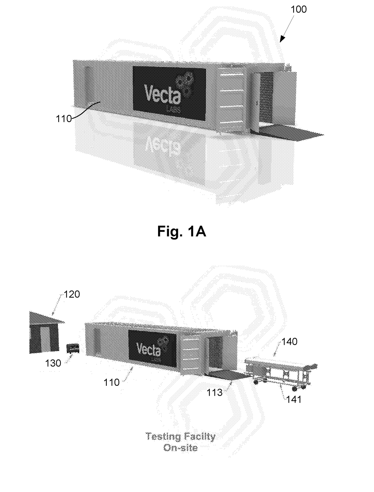
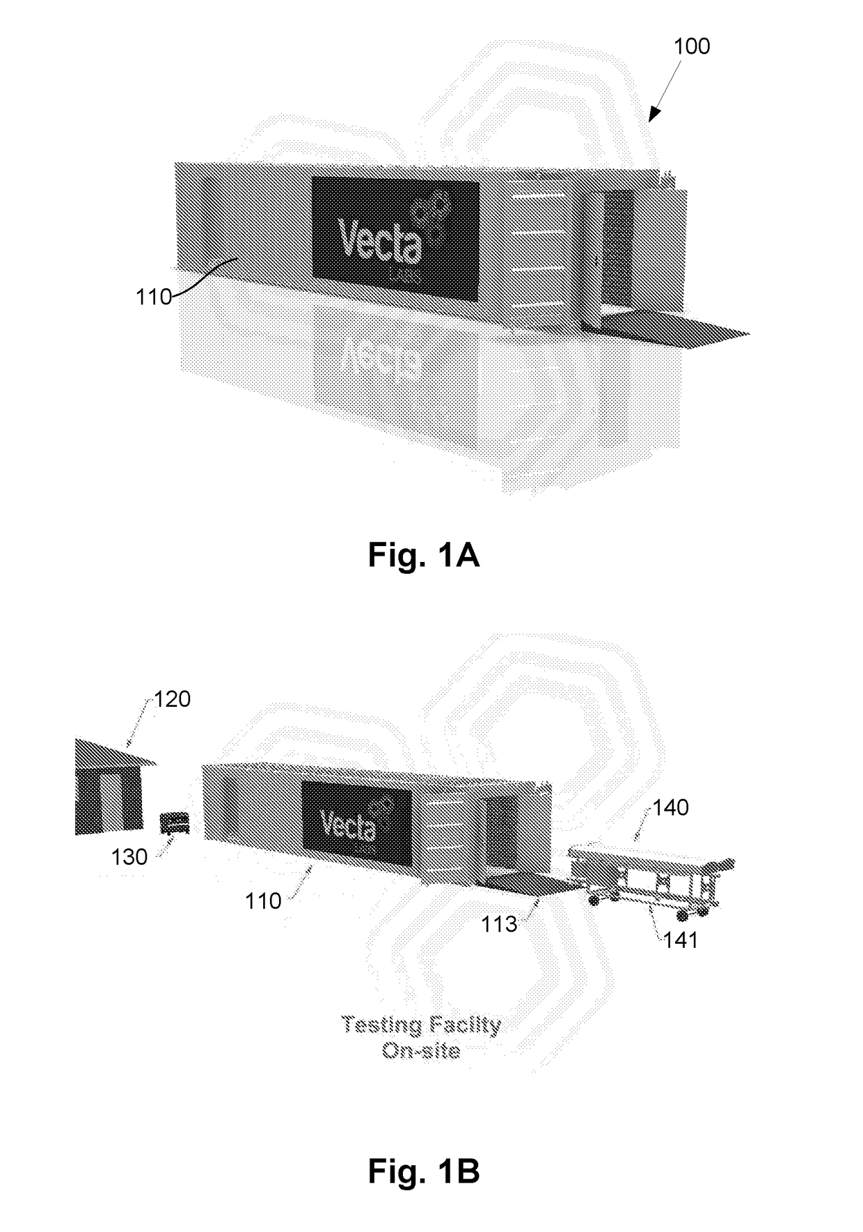
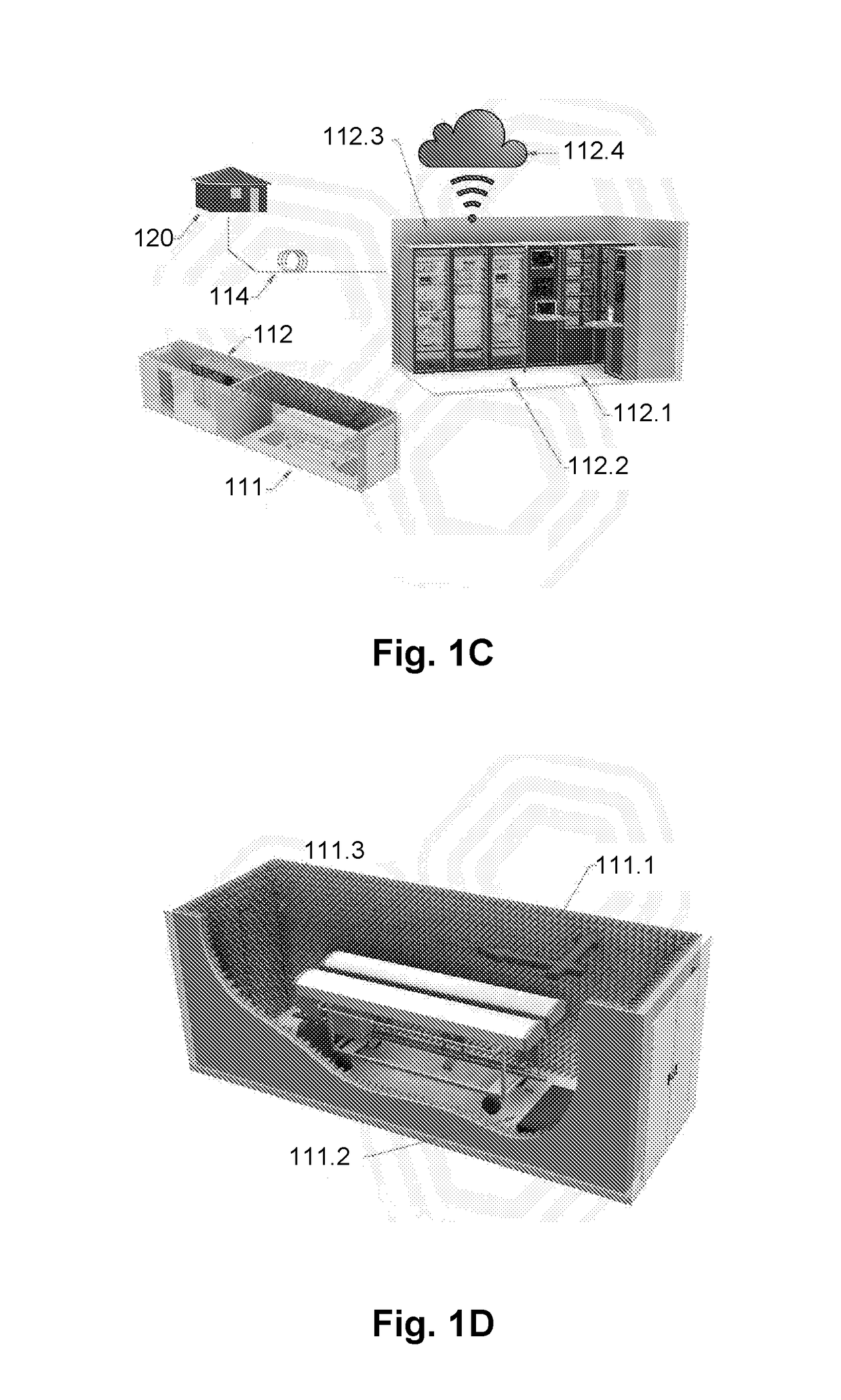
[0125]An example of a testing facility for testing sector or other similar telecommunications antennas and antenna assemblies will now be described with reference to FIGS. 1A to 1F.

[0126]For the purpose of clarity, the following description will use the term “antenna” to refer collectively to sector or other similar telecommunications antennas, as well as antenna assemblies, and use of the term antenna is not intended to be limited to single antennas.

[0127]In this example, the antenna testing apparatus includes a transportable container 110 including a testing chamber 111 that receives an antenna, including an antenna or antenna assembly, to be tested and an instrument room 112 containing test equipment for use in testing the antenna. In use, the antenna 140 is tested by moving the antenna into the testing chamber 111, and testing the antenna at least in part, by having the antenna generate RF signals and monitoring the generated RF signals, for example using the test equipment.

[012...


PUM


Abstract

An antenna testing apparatus including a transportable container having a testing chamber that receives an antenna or antenna assembly to be tested in use and an instrument room containing test equipment for use in testing the antenna or antenna assembly.

Description

BACKGROUND OF THE INVENTION[0001]The present invention relates to a method and apparatus for testing an antenna or antenna assembly and in one particular example to an antenna sector assembly for use at a mobile telecommunications network base station site.DESCRIPTION OF THE PRIOR ART[0002]The reference in this specification to any prior publication (or information derived from it), or to any matter which is known, is not, and should not be taken as an acknowledgment or admission or any form of suggestion that the prior publication (or information derived from it) or known matter forms part of the common general knowledge in the field of endeavour to which this specification relates.[0003]In the mobile communications industry, a base station is an installation that operates so to transmit and receive signals from telecommunication devices such as mobile phones or the like. Base stations typically radiate transmit and receive wireless signals through antennas. One example of an anten...

Claims


Application Information

Patent Timeline
IPC IPC(8): G01R29/10H01Q1/24H04B17/16G01M7/02H04B17/10
CPCG01R29/105G01M7/022H01Q1/24H04B17/16H04B17/102
Inventor SYMES, MICHAEL JOHN
Owner VECTA
Learn More