
Pattern-based camera pose estimation system

Active Publication Date: 2017-04-27
THE BOEING CO
View PDF5 Cites 28 Cited by
  • Summary
  • Abstract
  • Description
  • Claims
  • Application Information

AI Technical Summary

Benefits of technology

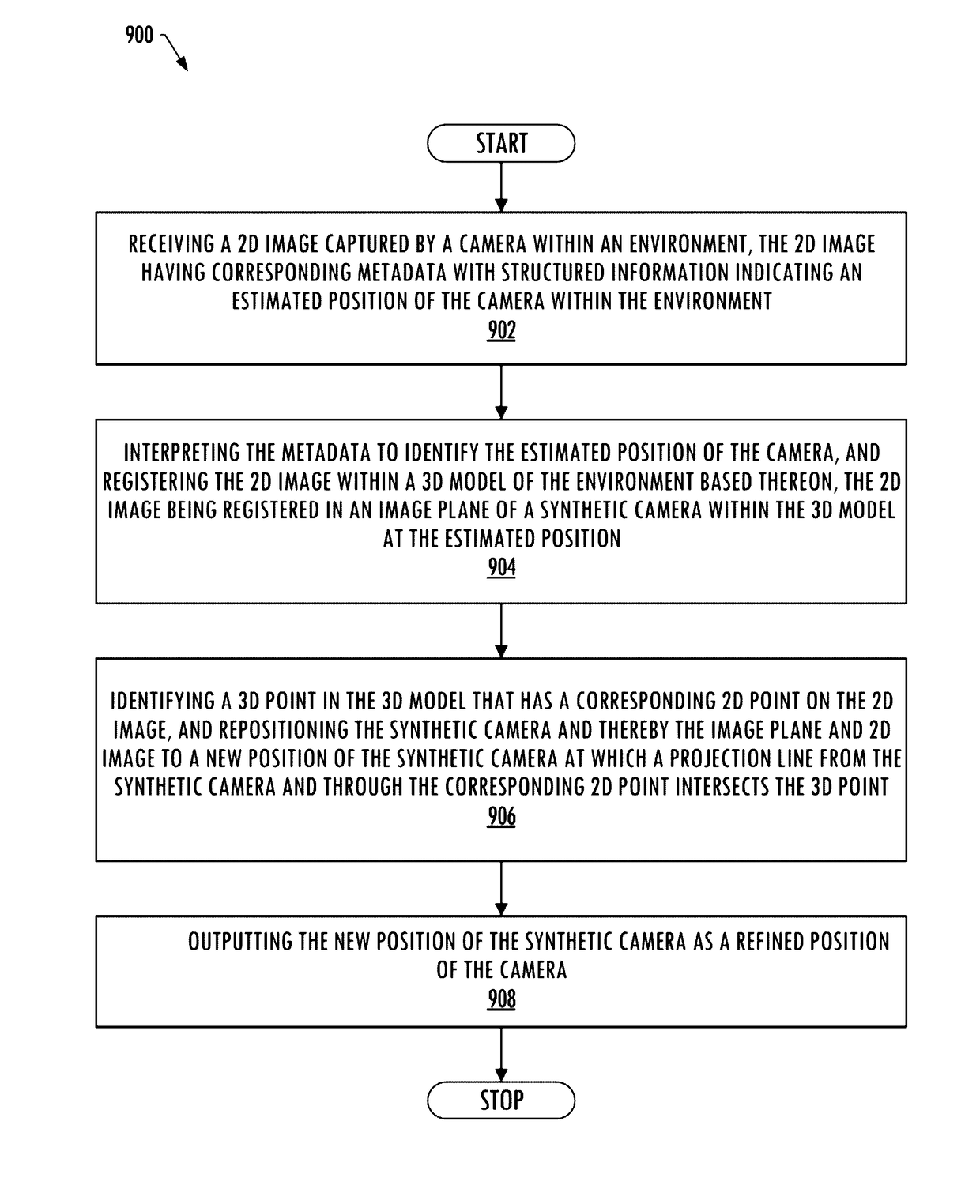
The present patent is about an improved method for estimating the position of a camera within an environment. The method involves receiving a 2D image of the environment and a 3D model of the environment. The 2D image is then analyzed to identify the position of the camera within the 3D model. This is done by interpreting the 2D image and identifying a point on the 2D image that matches a point in the 3D model. The method can use a variety of techniques, such as SIFT, POSIT, or pattern matching, to determine the position of the camera. The 2D image can be captured by a camera mounted on an unmanned aerial vehicle or a live video feed. The 3D model can be created using satellite imagery, elevation maps, or other 3D feature data. The method can also involve overlaying the 2D image onto the 3D model. The technical effect of this patent is to provide a more accurate and efficient way to estimate the position of a camera within an environment.

Problems solved by technology

In particular, the position and orientation data may be erroneous due to low frequency sampling, interferences, and the like.
However, many times, the required number of points of correlation may be unavailable, resulting in the algorithm being unable to determine the position of the camera.

Method used


Image

  • Pattern-based camera pose estimation system
  • Pattern-based camera pose estimation system
  • Pattern-based camera pose estimation system

Examples


Embodiment Construction

[0026]Some implementations of the present disclosure will now be described more fully hereinafter with reference to the accompanying drawings, in which some, but not all implementations of the disclosure are shown. Indeed, various implementations of the disclosure may be embodied in many different forms and should not be construed as limited to the implementations set forth herein; rather, these example implementations are provided so that this disclosure will be thorough and complete, and will fully convey the scope of the disclosure to those skilled in the art. For example, unless otherwise indicated, reference something as being a first, second or the like should not be construed to imply a particular order. Also, something may be described as being above something else (unless otherwise indicated) may instead be below, and vice versa; and similarly, something described as being to the left of something else may instead be to the right, and vice versa. Like reference numerals ref...


PUM


Abstract

A camera pose estimation system is provided for estimating the position of a camera within an environment. The system may be configured to receive a 2D image captured by a camera within the environment, and interpret metadata of the 2D image to identify an estimated position of the camera. A synthetic 2D image from a 3D model of the environment may be rendered by a synthetic camera within the model at the estimated position. A correlation between the 2D image and synthetic 2D image may identify a 2D point of correlation, and the system may project a line from the synthetic camera through the 2D point on the synthetic 2D image rendered in an image plane of the synthetic camera such that the line intersects the 3D model at a corresponding 3D point therein. A refined position may be determined based on the 2D point and corresponding 3D point.

Description

TECHNOLOGICAL FIELD[0001]The present disclosure relates generally to estimating a pose of a camera and, in particular, to determining the estimated pose of the camera using pattern matching.BACKGROUND[0002]During aerial video and / or image registration to a known three-dimensional (3D) scene, an aircraft vehicle is flown over a location and a live video feed or still images are captured of an environment. By determining the pose of the camera (e.g., where the camera was pointed) at the time the images where captured, the individual frames of the video feed or the still images can then be projected onto a 3D terrain within a virtual world to depict a visualization of the ground as imaged from the perspective of the aircraft vehicle.[0003]A camera pose typically defines the position and orientation of a camera within an environment. In some instances, the camera position can be determined through a hardware camera tracking system in which a magnetic and / or optical tracker is placed on ...

Claims


Application Information

Patent Timeline
IPC IPC(8): G06T7/00G06K9/00B64D47/08G06F17/30B64C39/02G06K9/62H04N5/225G06V20/13
CPCG06T7/004G06K9/6202G06K9/0063H04N5/225B64C2201/127G06F17/30277B64C39/024B64D47/08G06T2207/30244G06F17/30256G06T2207/10032G06T7/75G06F16/532G06F16/5838G06V20/13G06V10/757B64U2101/30B64U20/87G06T7/70
Inventor AUGHEY, JOHN H.
Owner THE BOEING CO
Learn More