Image display device and method using unidirectional beam

a display device and unidirectional technology, applied in the direction of static indicating devices, instruments, portable computers, etc., can solve the problems of increasing the difficulty of manufacturing and driving an image display device, increasing the power consumption when in use, etc., to achieve the reduction of the number of pixels necessary for displaying an image, the effect of increasing the manufacturing productivity of the image display device and being convenient to implemen

Active Publication Date: 2017-04-27
SAMSUNG ELECTRONICS CO LTD
View PDF4 Cites 16 Cited by
  • Summary
  • Abstract
  • Description
  • Claims
  • Application Information

AI Technical Summary

Benefits of technology

[0025]The above-described image display device may form an image by using a unidirectional beam with no diffusion, and may directly irradiate the image onto a retina of a user. Thus, even if the image display device is very close to an eye of the user, the user may recognize the image of the image display device, and thus a display device may be implemented in the form of a contact lens.
[0026]The image formed by using the unidirectional beam with no diffusion may be directly irradiated onto the retina, and thus a crystalline lens for recognizing the image may not be adjusted. That is, an image other than the image formed by the above-described image display device may be recognized without interruption, and thus augmented reality (AR) may be easily implemented by utilizing the above-described image display device as an additional image display device.
[0027]A pixel layout may be adjusted such that an image is focused at a high density in a retina central portion of a retina and at a relatively low density in a peripheral portion of a retina, and thus the number of pixels necessary for displaying an image may be reduced. Therefore, manufacturing productivity of the image display device may be increased, and power consumption may be reduced when in use.

Problems solved by technology

As the resolution is increased, many pixels of a smaller size need to be formed, thus increasing difficulty in manufacturing and driving an image display device, as well as increasing power consumption when in use.

Method used


Image

  • Image display device and method using unidirectional beam
  • Image display device and method using unidirectional beam
  • Image display device and method using unidirectional beam

Examples


Embodiment Construction

Technical Problem

[0005]The present disclosure provides an image display device of a structure in which the number of pixels used to display an image is reduced by using a human visual recognition characteristic.

Technical Solution

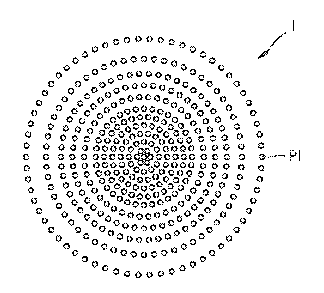
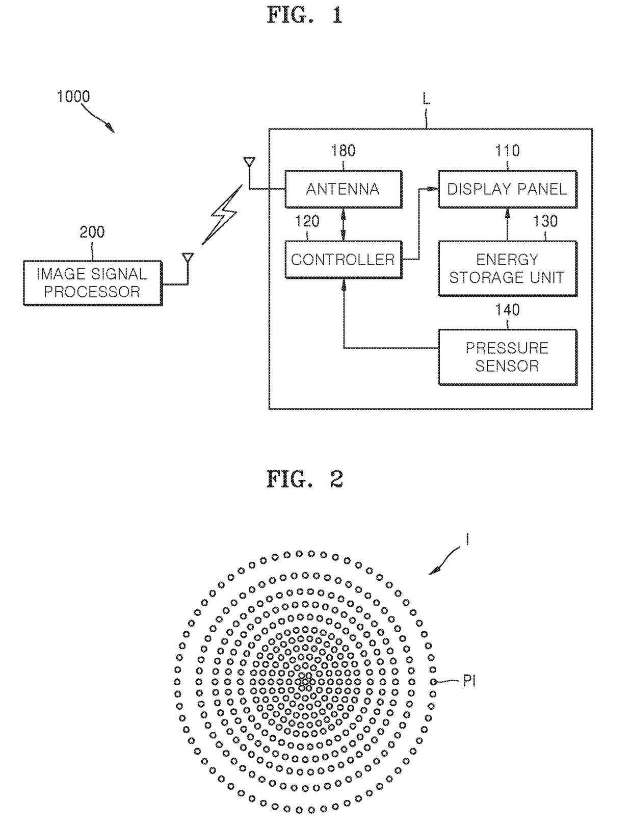
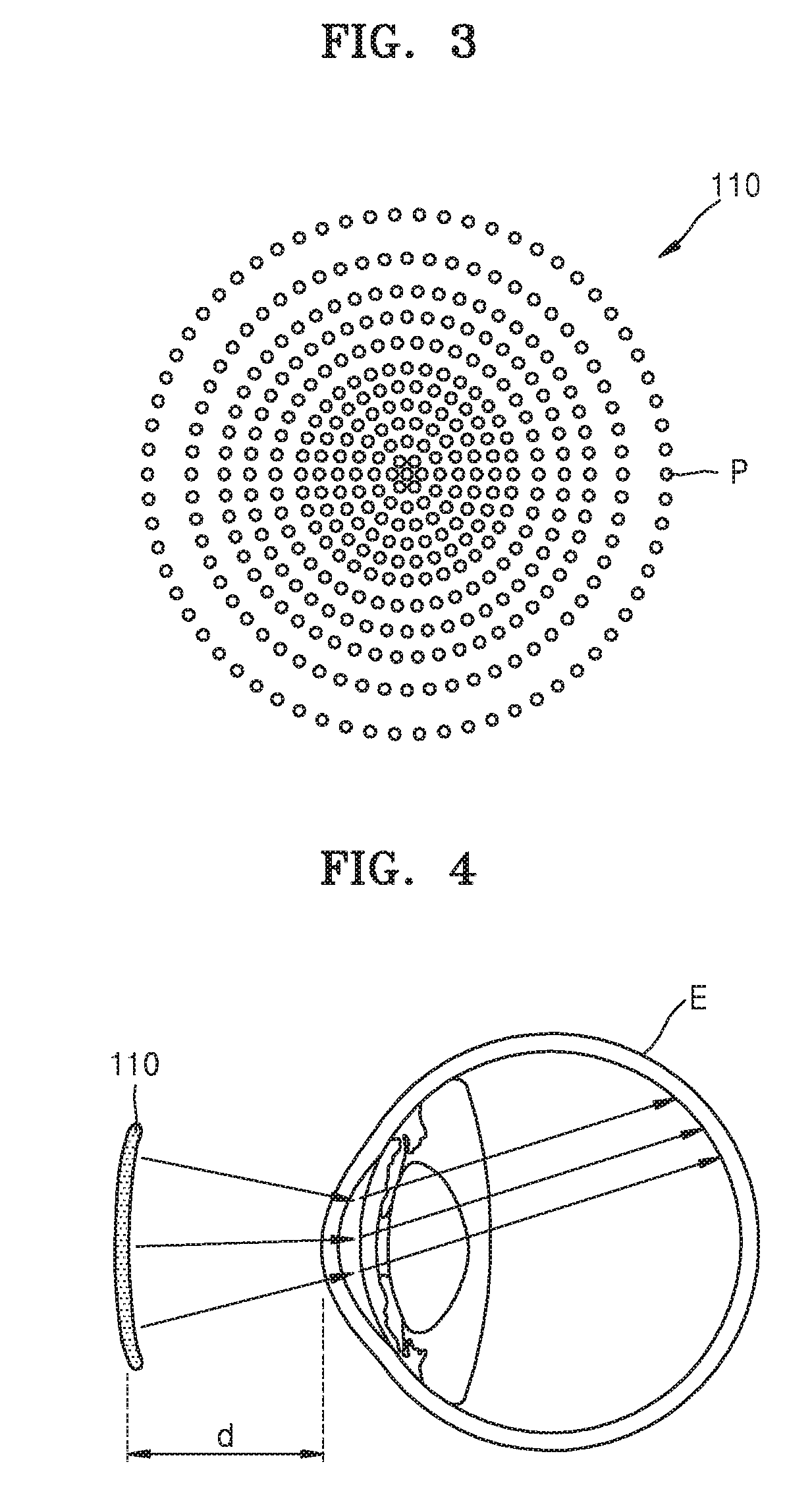
[0006]An image display device comprises an eye wearable lens; a display panel embedded inside the eye wearable lens or arranged on a surface of the eye wearable lens, the display panel comprising an array of a plurality of optical elements for forming an image to be projected onto a retina, wherein a resolution of the image formed by the plurality of optical elements is higher on a central portion of the retina than on a peripheral portion of the retina; and an image signal processor for generating an image signal according to image information which is to be displayed on the display panel and for generating a control signal for controlling each of the plurality of optical elements to be turned on / off according to the image signal.

[0007]The plurality of opti...


PUM


Abstract

An image display device includes an eye wearable lens; a display panel embedded inside the eye wearable lens or arranged on a surface of the eye wearable lens, the display panel comprising an array of a plurality of optical elements for forming an image to be projected onto a retina, wherein a resolution of the image formed by the plurality of optical elements is higher on a central portion of the retina than on a peripheral portion of the retina; and an image signal processor for generating an image signal according to image information which is to be displayed on the display panel and for generating a control signal for controlling each of the plurality of optical elements to be turned on/off according to the image signal.

Description

TECHNICAL FIELD[0001]The present disclosure relates to an image display device using a unidirectional beam.BACKGROUND ART[0002]An image display device has been widely used in various fields such as advertising, games, healthcare, culture, etc.[0003]Recently, the size of pixels in image display devices has been gradually reduced in order to implement a high resolution. The structure of image display devices has been changed in various ways in order to provide a 3-dimensional (3D) image and an augmented reality (AR) image.[0004]When the 3D image or the AR image is implemented, a great amount of data needs to be processed as compared with when a 2D image is implemented. As the resolution is increased, many pixels of a smaller size need to be formed, thus increasing difficulty in manufacturing and driving an image display device, as well as increasing power consumption when in use.DETAILED DESCRIPTION OF THE INVENTIONTechnical Problem[0005]The present disclosure provides an image displa...

Claims


Application Information

Patent Timeline
Patent Type & Authority Applications(United States)
IPC IPC(8): G09G3/00G06T3/40G09G5/391G02C7/04G06F3/01
CPCG09G3/002G02C7/041G06F3/013G09G2340/0407G06T3/40G09G2354/00G09G5/391G02B27/02G02C7/04G06F1/163G06F3/011G06F3/147G06T3/0012G02C7/02
Inventor AHN, HOYOUNGKIM, JUNGWOOKIM, TAEHOCHOI, BYOUNGLYONGHWANG, SUNGWOOKIM, SANGWONCHUNG, DAEYOUNGKU, JIYEON
Owner SAMSUNG ELECTRONICS CO LTD
Why Eureka
Try Eureka