
Systems and methods for mitigating harmonics in electrical systems by using active and passive filtering techniques

a technology of active and passive filtering and electrical systems, applied in the direction of reducing harmonics/ripples in the ac network, emergency power supply arrangements, instruments, etc., can solve the problems of reducing system efficiency and disturbance of the operation of nearby loads at points of common coupling (pcc) of the grid, and achieve the effect of reducing harmonics

Active Publication Date: 2017-04-27
INERTECH IP
View PDF4 Cites 13 Cited by
  • Summary
  • Abstract
  • Description
  • Claims
  • Application Information

AI Technical Summary

Benefits of technology

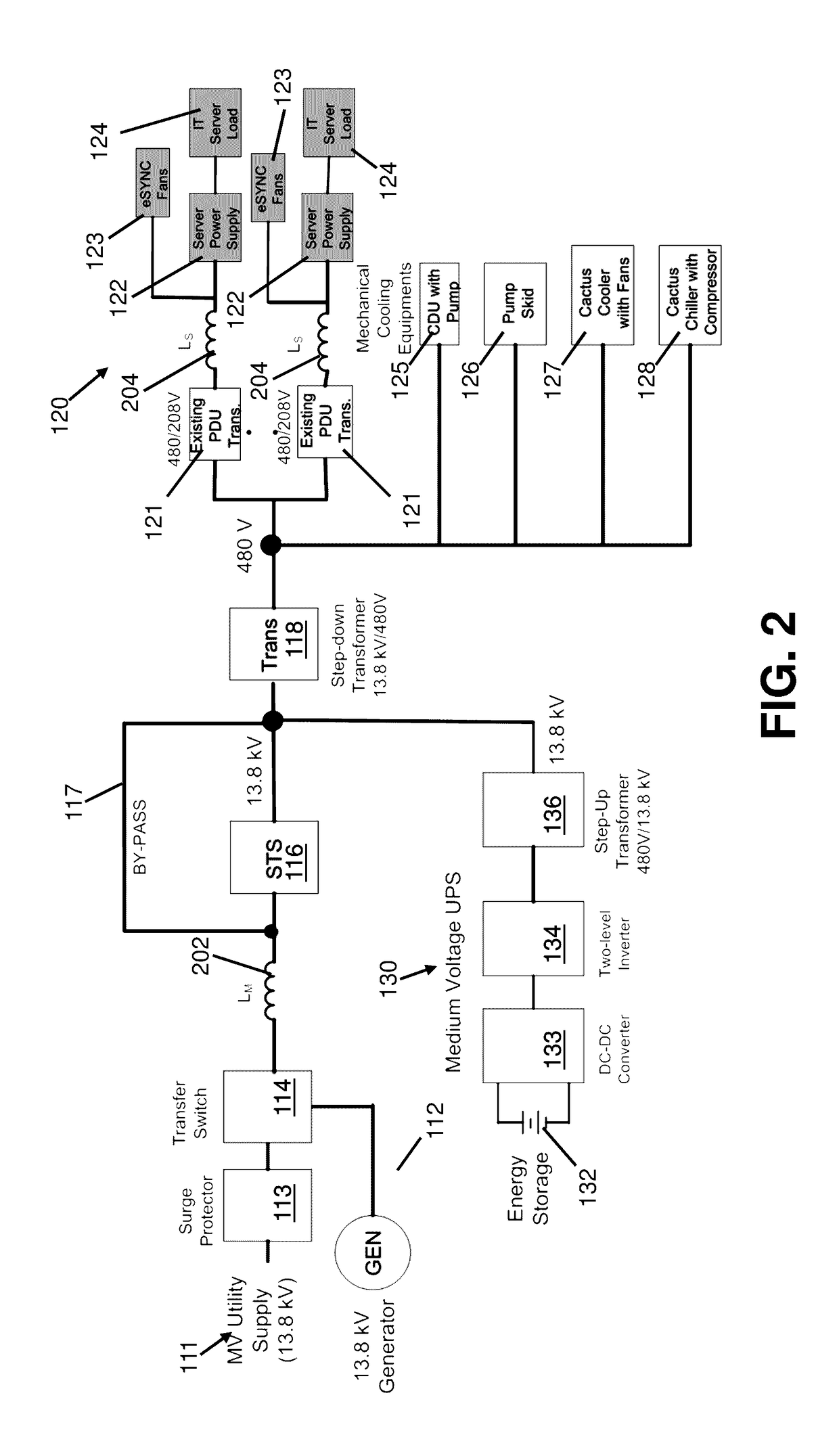
The present disclosure describes an electrical system that includes power distribution unit (PDU) transformers, a line reactor, a multi-level inverter, a DC-DC converter, and an energy storage device. The PDU transformers are connected to server power supplies and fan variable frequency drives. The system also includes a controller that filters load currents to obtain harmonic portions and controls the active filters to generate harmonic currents. The system can compensate for harmonic currents and provide uninterruptible power in the event of an interruption in power. The technical effects of the system include improved power distribution, reduced harmonic currents, and improved stability and reliability.

Problems solved by technology

Current and voltage harmonics, which are current and voltage signals having frequencies that are an integer multiple of the fundamental frequency, contribute to losses and reduces system efficiency.
Operation of nearby loads at points of common coupling (PCC) of the grid will be disturbed in case the DC draws a large amount of harmonic currents from the grid.

Method used


Image

  • Systems and methods for mitigating harmonics in electrical systems by using active and passive filtering techniques
  • Systems and methods for mitigating harmonics in electrical systems by using active and passive filtering techniques
  • Systems and methods for mitigating harmonics in electrical systems by using active and passive filtering techniques

Examples


Embodiment Construction

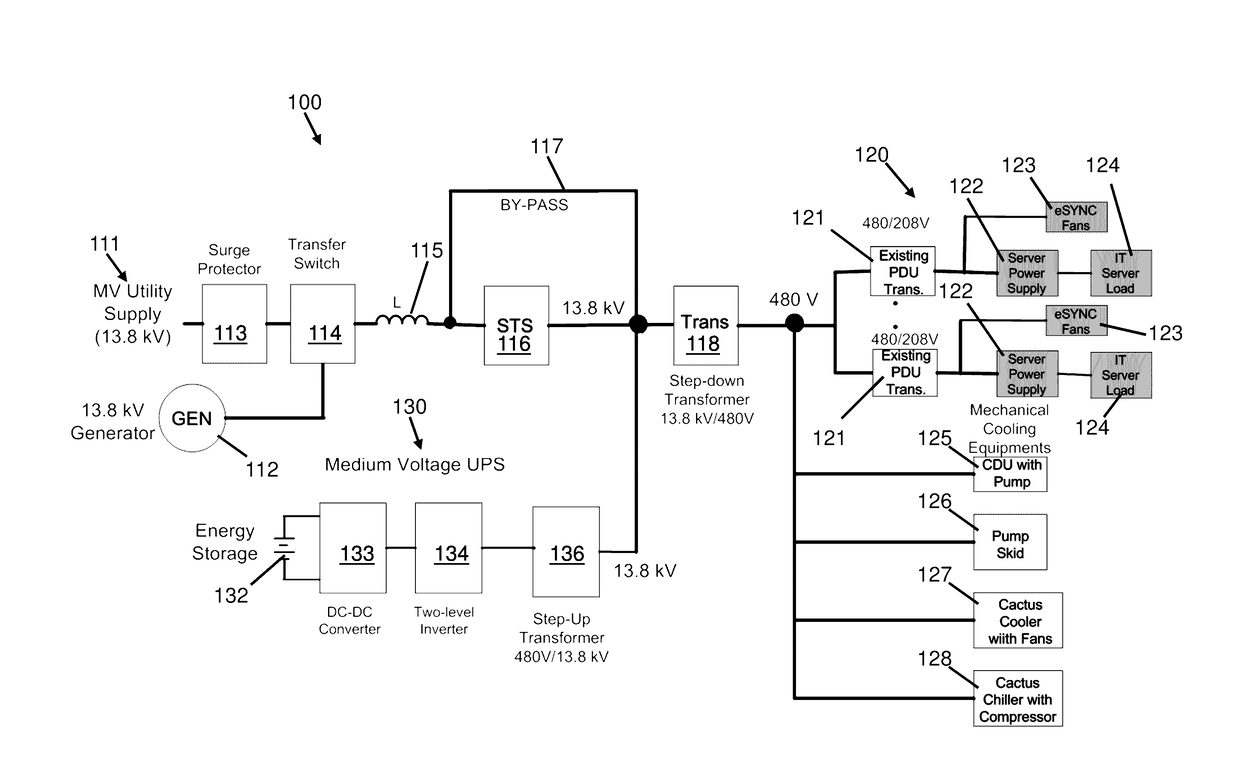
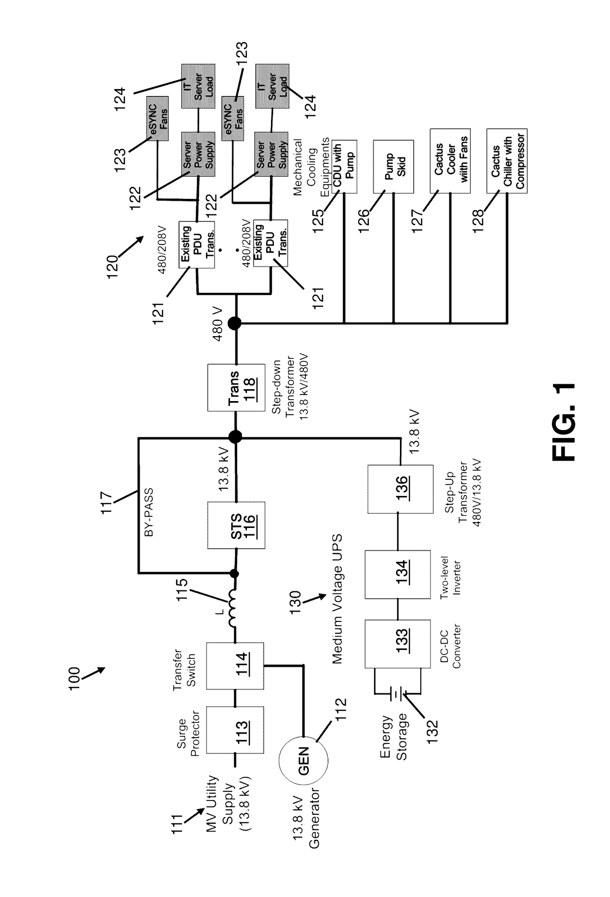
[0039]FIG. 1 shows an existing MV DC electrical system for supplying power to server and mechanical cooling loads. The system includes a utility / generator power supply system and a MVUPS 130, a shunt connected Voltage Source Inverter (VSI) with battery energy storage 132 that includes a step-up transformer 136 for MV applications. The system also incorporates a line reactor L 115 located at the MV distribution point to mitigate line current harmonics at the grid. The line reactor L is coupled to an AC MV line to reduce harmonics in the power supplied by the MV utility supply 111 or generator supply 112. Line reactor L 115 is in the passive filtering mode. A step-down transformer 118 is disposed in series with the IT load 120 and the mechanical cooling loads, i.e., a cooling distribution unit (CDU) having a pump 125, a pump skid having multiple pumps 126, a fluid cooler having fans 127, and a chiller having a compressor 128. The IT server load 120 is connected to an AC-DC-DC switchin...


PUM


Abstract

Systems and methods of the present disclosure involve passive, hybrid, and active filtering configurations to mitigate current harmonics for various electrical loads. One hybrid filtering configuration is medium voltage (MV) active filtering using a DC-DC converter and a multi-level inverter, and low voltage (LV) passive filtering. Another hybrid filtering configuration is MV passive filtering and LV active filtering using a two-level inverter. An active filtering configuration includes both MV and LV active filtering. The present disclosure also features power distribution unit (PDU) transformers electrically coupled to respective power supplies on the LV side of an electrical system. Each PDU transformer includes primary coils in a delta configuration and secondary coils in a wye configuration. The secondary coils are in series with respective leakage inductance coils. The secondary coils and the leakage inductance coils are integrated together into a single unit or module.

Description

BACKGROUND[0001]1. Technical Field[0002]The present disclosure generally relates to harmonic mitigation techniques. More particularly, the present disclosure relates to active and passive hybrid filtering techniques to mitigate line harmonics.[0003]2. Background of Related Art[0004]Current and voltage harmonics, which are current and voltage signals having frequencies that are an integer multiple of the fundamental frequency, contribute to losses and reduces system efficiency. In the case of data centers (DCs), a small amount of permissible harmonic current increases the life of data center equipment, reduces malfunction of DSP controllers, reduces safety hazards, and reduces or eliminates potential penalties imposed by the utility because of large amounts of harmonic current, which may affect other loads connected at the point of common coupling (PCC). DCs are one of the largest and fastest growing consumers of electricity in the world. In 2013, DCs residing in the United States co...

Claims


Application Information

Patent Timeline
Patent Type & Authority Applications(United States)
IPC IPC(8): H02J9/06H02M7/537H02M1/12H02M3/158
CPCH02J9/061H02M1/12H02M7/537H02M3/158Y02E40/40H02J3/01H02J3/1857H02J3/28H02J3/32H02M7/487Y02E40/20
Inventor MONDAL, SUBRATA K.
Owner INERTECH IP
Learn More