Flexible device and fabrication method thereof, display apparatus

a flexible device and fabrication method technology, applied in the field of display technologies, can solve the problems of relative high laser energy and power consumption, and achieve the effect of reducing laser energy

Active Publication Date: 2017-05-04
BOE TECH GRP CO LTD
View PDF4 Cites 3 Cited by
  • Summary
  • Abstract
  • Description
  • Claims
  • Application Information

AI Technical Summary

Benefits of technology

[0006]The present disclosure is at least able to reduce the laser energy during the de-bonding process for separating substrate from a flexible device and a.
[0007]One aspect of the present disclosure includes providing a method for fabricating a flexible apparatus. The method includes providing substrate; forming a sacrificial layer on the substrate; forming a reflective layer over at least a portion of sacrificial layer; forming a flexible device over the reflective layer; and separating the substrate from the flexible device by irradiating the sacrificial layer using laser, wherein the reflective layer is arranged to reflect laser back to the sacrificial layer, thereby reducing laser energy required for separating the substrate.
[0019]According to the disclosed embodiments, during the de-bonding process for separating a substrate from a flexible device and by a laser release method, because a reflective layer is formed on at least a portion of the sacrificial layer; and the reflective layer is able to reflect the irradiating laser back to the sacrificial layer, the energy of the laser absorbed by the sacrificial layer may be increased. Thus, the required laser energy for the de-bonding process may be reduced. Further, the laser may not need to be adjusted during the de-boning process. Thus, the production efficiency may be increased.

Problems solved by technology

Therefore, it may need relatively high laser energy to separate the rigid substrate from the flexible devices; and the power consumption may be relatively high.

Method used


Image

  • Flexible device and fabrication method thereof, display apparatus
  • Flexible device and fabrication method thereof, display apparatus
  • Flexible device and fabrication method thereof, display apparatus

Examples


Embodiment Construction

[0025]For those skilled in the art to better understand the technical solution of the invention, reference will now be made in detail to exemplary embodiments of the invention, which are illustrated in the accompanying drawings. Wherever possible, the same reference numbers will be used throughout the drawings to refer to the same or like parts.

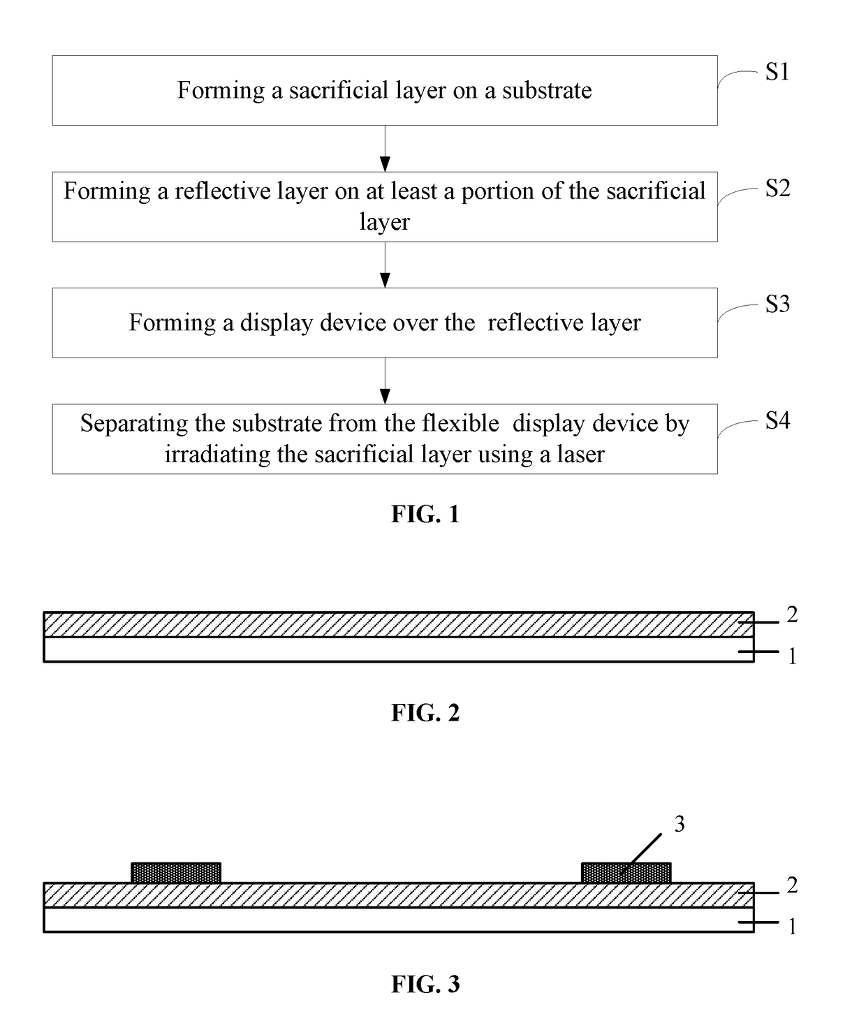
[0026]According to the disclosed embodiments, a method for fabricating a flexible device is provided. FIG. 1 illustrates an exemplary fabrication process of a flexible device according to the disclosed embodiments.

[0027]As shown in FIG. 1, at the beginning of the fabrication process, a substrate is provided; and a sacrificial layer is formed on the substrate (S1). FIG. 2 illustrates a corresponding structure.

[0028]As shown in FIG. 2, a substrate 1 is provided, and a sacrificial layer 2 is formed on the substrate 1. The substrate 1 may be made of any appropriate material, such as silicon, quartz, rigid plastic, or glass, etc. In one embodiment...


PUM

PropertyMeasurementUnit
temperatureaaaaaaaaaa
thicknessaaaaaaaaaa
thicknessaaaaaaaaaa

Abstract

A method for fabricating a flexible device is provided. The method includes forming a sacrificial layer on a substrate; and forming a reflective layer to reflect a laser for subsequently de-bonding the sacrificial layer from the rigid substrate back to the sacrificial layer to reduce required de-bonding energy of the laser over at least a portion of the rigid substrate. Further, the method includes forming a flexible device over the reflective layer; and separating the substrate from the sacrificial layer by irradiating the sacrificial layer using the laser.

Description

CROSS-REFERENCES TO RELATED APPLICATIONS[0001]This PCT patent application claims priority of Chinese Patent Application No. 201510138382.9, filed on Mar. 26, 2015, the entire contents of which are incorporated by reference herein.FIELD OF THE INVENTION[0002]The present invention generally relates to the field of the display technologies and, more particularly, to a flexible device and fabrication processes thereof, and a display apparatus.BACKGROUND[0003]Currently, the manufacturing process for flexible electronic devices often includes a roll-to-roll process or a sheet-by-sheet process. The sheet-by-sheet process is able to better utilize the existing manufacturing processes and equipment for manufacturing LCD display panels. Specifically, the sheet-by-sheet process includes, sequentially, providing a rigid substrate as a carrier; forming a flexible device on the rigid substrate; and separating the formed flexible device from the rigid substrate.[0004]One of the methods for separat...

Claims


Application Information

Patent Timeline
Patent Type & Authority Applications(United States)
IPC IPC(8): B32B38/10B32B37/14B32B27/28H01L51/00
CPCB32B38/10H01L51/003B32B37/14B32B27/281B32B2255/10H01L2227/326H01L27/3244B32B2255/26B32B2457/206H01L2251/5338H01L21/02365H01L21/683H01L21/6835H01L2221/68318H01L2221/6835H01L2221/68381G02F1/133305H01L21/7806H10K59/12H10K71/80H10K59/1201H10K2102/311
Inventor LIU, LUHSIEH, MING CHE
Owner BOE TECH GRP CO LTD
Why Eureka
Try Eureka