Detecting nanoparticles on production equipment and surfaces

Active Publication Date: 2020-03-05
PARTICLE MEASURING SYST
View PDF4 Cites 5 Cited by
  • Summary
  • Abstract
  • Description
  • Claims
  • Application Information

AI Technical Summary

Benefits of technology

[0012]Optical particle counters use scattered, obscured or emitted light to detect particles. The optical particle counter may utilize condensation particle counting systems or split detection optical particle counters to increase the sensitivity of the device (thereby allowing for the detection of smaller particles) while avoiding the increased complexity typically required for the detection of nanoscale particles, e.g., particles less than 100 nm in effective diameter.
[0013]The use of condensation particle counters for the application of surface removal and detection may be advantageous over other types of particle counters or analyzers (e.g. scattered or obscured light detectors) due to the lower power requirements provided by condensation particle counters. While condensation particle counters may use a similar form of light detection (e.g. scattered, obscured), the ability of the condensation aspect of the particle counter to increase the effective size (i.e. effective diameter, volume) of the particles by condensing a liquid on the surface of the particle means that the detection system needs only be capable of detecting an enla

Problems solved by technology

Smaller particles, specifically particles less than 100 nm, can pose additional difficulties for maintaining a cleanroom environment because they are much more likely to interact or adhere to a surface within the cleanroom environment due to electrostatic, physical, chemical or magnetic forces between the particle and the surface.
For examples, tools and other devices may need to be removed from

Method used


Image

  • Detecting nanoparticles on production equipment and surfaces
  • Detecting nanoparticles on production equipment and surfaces

Examples


example 1

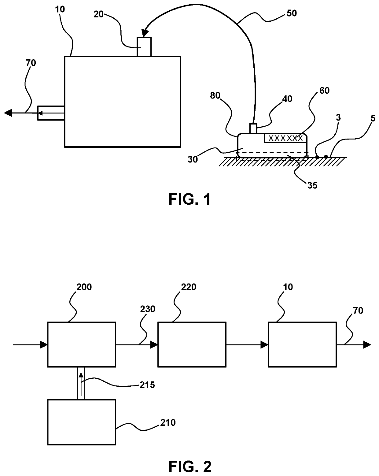
[0045]This example demonstrates a condensation particle counter with an attached ejection and sampling device (e.g. a sample puck or wand).

[0046]Described herein are systems and methods for monitoring of particles adhering to surfaces by adapting a condensation particle counter with a sample puck. The device generates a metered flow of filtered clean air and delivers it to the sample puck for dislodging particles from a surface. The resultant air stream with dislodged particles is then pulled from the sample puck into the condensation particle counter with a vacuum system. The vacuum system may utilize a matching flow rate to the dislodging flow rate. As particle size reduces, electrostatic and stiction characteristics make the particles progressively harder to eject from the surface for potential collection and counting. More aggressive particle removal techniques may be used to effectively remove them from surfaces. Some example removal techniques include: Metered air flow; Therma...


PUM


Abstract

Provided herein is a particle analyzer that is operably connected to a probe unit that is capable of both dislodging particles from a surface and sampling the particles after they have been dislodged. The devices and methods described herein may be lightweight and/or handheld, for example, so that they may be used within a cleanroom environment to clean and sample permanent surfaces and tools. The devices may include optical particle counters that use scattered, obscured or emitted light to detect particles, including condensation particle counting systems or split detection optical particle counters to increase the sensitivity of the device and thereby facilitate detection of smaller particles, while avoiding the increased complexity typically required for the detection of nanoscale particles, such as particles less than 100 nm in effective diameter.

Description

CROSS REFERENCE TO RELATED APPLICATIONS[0001]This application claims the benefit of priority to U.S. Provisional Patent Application No. 62 / 726,851 filed Sep. 4, 2018, which is incorporated herein by reference in its entirety to the extent not inconsistent herewith.BACKGROUND OF THE INVENTION[0002]Advancement of the various technologies requiring cleanroom manufacturing has led to a desire for the detection of smaller and smaller particles. Both microelectronic foundries and pharmaceutical / biological cleanrooms are beginning to seek detection of particles less than 20 nm in size as they may affect the increasingly sensitive manufacturing processes.[0003]Smaller particles, specifically particles less than 100 nm, can pose additional difficulties for maintaining a cleanroom environment because they are much more likely to interact or adhere to a surface within the cleanroom environment due to electrostatic, physical, chemical or magnetic forces between the particle and the surface. At ...

Claims


Application Information

Patent Timeline
IPC IPC(8): G01N15/06G01N21/05
CPCG01N2015/0038B82Y35/00G01N15/065G01N21/05G01N1/02G01N2001/028G01N2001/002G01N15/14
Inventor KNOLLENBERG, BRIAN A.RODIER, DANIEL ROBERT
Owner PARTICLE MEASURING SYST
Why Eureka
Try Eureka