High power laser beam expander

A laser beam and high-power technology, applied in the field of beam expanders, can solve the problems of not disclosing the working principle of the internal optical path, the unfavorable miniaturization of the laser emission system, and the poor pointing stability of the laser beam, so as to improve the laser damage threshold, Effect of reducing laser energy density and improving stealth ability

Inactive Publication Date: 2008-12-10
南瑶
View PDF1 Cites 8 Cited by
  • Summary
  • Abstract
  • Description
  • Claims
  • Application Information

AI Technical Summary

Problems solved by technology

Common problems in this type of laser system include: laser damage of optical components, poor uniformity of laser spot distribution, poor pointing stability of laser beam, and difficulty in ensuring the coaxiality of the optical axis between the laser and other photoelectric systems
This method involves mechanical structures, electrical sensors, real-time calculation of electrical signals and feedback drive circuits, and its design is complicated, which is not conducive to the miniaturization of the entire laser emission system
[0006] The traditional laser beam shaping methods include: the spatial filtering (mode selection) method of the laser output laser, the Gaussian distribution method of the reflectivity of the output mirror of the laser resonator, and the cosine correction method of opal glass; the latest product of laser beam shaping is Molecular Technology of Germany The beam shaper produced by the Gmbh company can convert the Gaussian beam output by the laser into a beam (πshaper) with a flat-top shape distribution. The working method of its internal optical path and the working principle of the device are not disclosed

Method used


Image

  • High power laser beam expander
  • High power laser beam expander

Examples


Embodiment 1

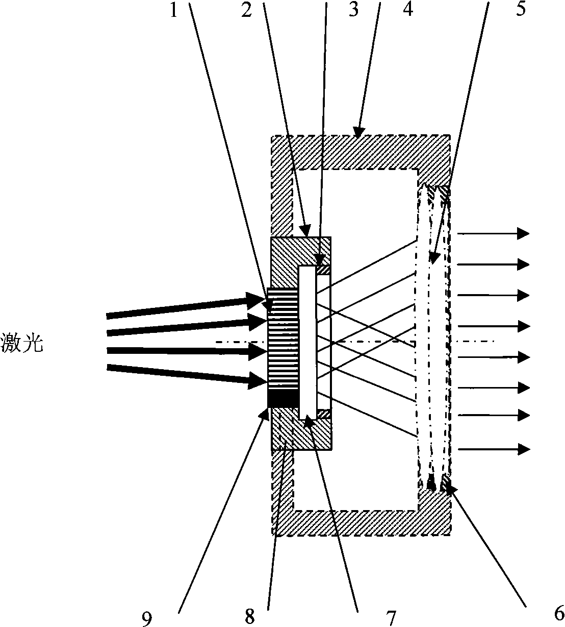
[0022] Embodiment 1 beam expander: according to figure 1As shown, the preferred embodiment of the present invention includes a beam expander 1 , a housing 2 , a mirror tube 4 , and an optical system 5 . The beam expander 1 is formed by a group of short bare single-mode optical fiber rods 11 of equal length closely arranged. The bare optical fiber rods are neatly arranged in the cylindrical shell 2 along the axial direction, and the input / output end faces of the optical fiber rods are strictly aligned. . A commercially available single-mode fiber is used for the fiber rod, and the coating layer of the single-mode fiber is removed, and the bare fiber is cut into small sections with a length of 5 mm with a special cutter. The housing 2 includes protective glasses 7 , a pressure ring 3 , a plurality of pressure pieces 9 and screws 8 . The shell 2 has one or more cylindrical tubes with axial grooves on the inner wall. The inner diameter of the cylindrical tubes is Φ12mm and the l...

Embodiment 2

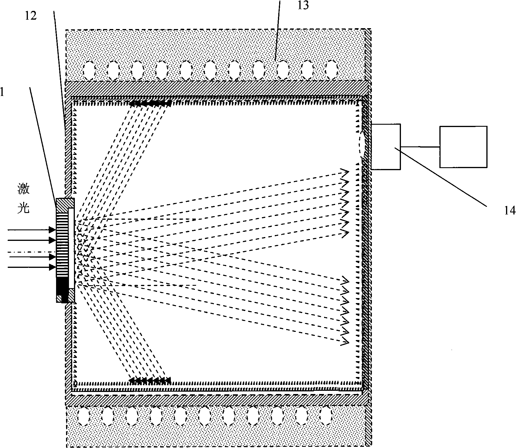
[0023] Embodiment 2 high-power laser parameter measuring device: according to figure 2 As shown, the preferred embodiment of the present invention includes a beam expander 1 , an absorption cavity 12 , a cooling system 13 , and a detection system 14 . The beam expander 1 is the same as the embodiment 1; the absorption cavity 12 is a cylindrical cavity, and the inner wall of the cavity is a zigzag absorption pattern, the beam expander 1 is installed in the center of a bottom surface of the cylindrical cavity, and the optical fiber of the beam expander 1 The direction of the optical axis of the rod is coaxial with the cylindrical cavity. The cooling system 13 is close to the absorption cavity 12, and is used for cooling the absorption cavity 12, so that the temperature of the absorption cavity 12 remains constant after absorbing the laser energy, and at the same time, the deformation of the cavity is reduced. The detection system 14 is composed of an interference filter, a det...


PUM

PropertyMeasurementUnit
The inside diameter ofaaaaaaaaaa
Lengthaaaaaaaaaa
Caliberaaaaaaaaaa

Abstract

The invention discloses a extender lens for expanding high power laser beams, which has the main technical characteristics that a plurality of optical fiber rods with equal lengths are all tightly arranged in the cavity body of a housing and the end surfaces of the optical fiber rods respectively form input faces and output faces; the optical fiber rods are bare optical fibers and can adopt optical fibers the core diameter of which is smaller than that of single mode fiber. The invention can expand the laser beans as well as shape and stabilize the direction of the laser beans, and has the advantages of high laser induced damage threshold, simple structure and great reduction of the volume and the weight of a laser shot system.

Description

technical field [0001] The present invention relates to a laser beam expander, mainly to a beam expander used in a high power density laser emission system, in particular to a beam expander capable of beam shaping and beam pointing stability for high power density repetition rate pulsed lasers device. Background technique [0002] With the development of laser technology, more and more applications of high-power repetition rate pulsed lasers in optoelectronic systems have become an important technical measure to improve the range and effectiveness of the entire optoelectronic weapon system. Common problems in this type of laser system include: laser damage of optical components, poor uniformity of laser spot distribution, poor pointing stability of laser beam, and difficulty in ensuring the coaxiality of the optical axis between the laser and other optoelectronic systems. These problems directly affect the normal performance of the laser system. [0003] The energy distrib...

Claims


Application Information

Patent Timeline
IPC IPC(8): G02B27/09G02B6/26
Inventor (请求不公开姓名)
Owner 南瑶
Why Eureka
Try Eureka