Controlling cooling flow in a cooled turbine vane or blade using an impingement tube

a technology of impingement tube and turbine blade, which is applied in the direction of blade accessories, machine/engine, engine fuction, etc., can solve the problems of unfavorable cooling efficiency, unfavorable cooling of blades, and inability to cool metal, and achieve the effect of simple cooling mechanism

Active Publication Date: 2017-05-04
SIEMENS ENERGY GLOBAL GMBH & CO KG
View PDF12 Cites 4 Cited by
  • Summary
  • Abstract
  • Description
  • Claims
  • Application Information

AI Technical Summary

Benefits of technology

[0012]It may be an object to provide an airfoil for a gas turbine which comprises a simple cooling mechanism for cooling the airfoil.
[0031]Hence, by the approach of the present invention, customised first and second tail fins are formed and installed at the respective end sections of the first and second cooling channels. By the customised tail fins, the respective first and second mass flows of the cooling fluid may be adjusted to a desired ratio. Specifically, the customised first and second tail fins may adjust the first mass flow and the second mass flow in such a way that the first mass flow is equal (at least in one predefined operating state of the gas turbine) to the second mass flow such that the cooling fluid comprises the same cooling efficiency in the first cooling channel and in the second cooling channel. Hence, by comprising the second cooling efficiency of the cooling fluid along the high pressure side and long the low pressure side, thermal strain caused by sections with different temperatures is reduced and the lifetime of the inner shell and the outer shell, respectively, is increased.
[0042]According to a further exemplary embodiment, the airfoil further comprises a retaining element arranged within the common cooling channel downstream of the first tail fin. The retaining element is arranged such that the retaining element prevents a further deformation if a predetermined maximum deformation of the first tail fin is reached.
[0045]This is possible by the above described airfoil according to the present invention, because the mass flow through the respective cooling channels may be controlled by the respective tail fin such that only one fluid outlet at the nose section of the inner shell is sufficient for providing an adequate mass flow and hence a desired cooling effect.

Problems solved by technology

This results in unequal cooling efficiency and leads to hot metal temperatures in some regions and cool metal temperatures in others.
However, complex control mechanisms and the plurality of conventional fluid outlets 604, 702 are necessary and the efficiency of the cooling compromised.

Method used


Image

  • Controlling cooling flow in a cooled turbine vane or blade using an impingement tube
  • Controlling cooling flow in a cooled turbine vane or blade using an impingement tube
  • Controlling cooling flow in a cooled turbine vane or blade using an impingement tube

Examples


Embodiment Construction

[0054]The illustration in the drawings is in schematic form. It is noted that in different figures, similar or identical elements are provided with the same reference signs.

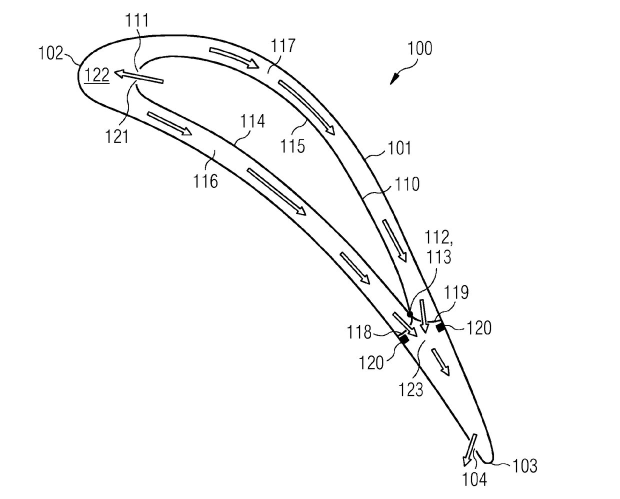
[0055]FIG. 1 shows a sectional view of an airfoil 100 according to an exemplary embodiment of the present invention. The airfoil 100 comprises an (hollow) outer shell 101 comprising an inner volume and an inner shell 110 arranged within the inner volume of the outer shell 101. The inner shell 110 comprises an aerodynamic profile having an inner nose section 111 and an inner tail section 112, wherein a high pressure side 114 of the inner shell 110 is formed along a first surface section between inner nose section 111 and the inner tail section 111 and a low pressure side of the inner shell 110 is formed along a second surface section which is located opposite to the first surface section between inner nose 111 section and the inner tail section 112.

[0056]The inner shell 110 is spaced apart from the outer shell 101...


PUM


Abstract

An airfoil for a gas turbine having an outer shell with an inner volume and an inner shell arranged within the inner volume of the outer shell, wherein the inner shell has an aerodynamic profile having an inner nose section and an inner tail section. A first cooling channel and a second cooling channel merge into a common cooling channel at an inner tail section. A first tail fin is arranged between the first cooling channel and the common cooling channel such that a first mass flow rate of the cooling fluid flowing through the first cooling channel is controllable. A second tail fin is arranged between the second cooling channel and the common cooling channel such that a second mass flow rate of the cooling fluid flowing through the second cooling channel is controllable.

Description

CROSS REFERENCE TO RELATED APPLICATIONS[0001]This application is the US National Stage of International Application No. PCT / EP2015 / 054912 filed Mar. 10, 2015, and claims the benefit thereof. The International Application claims the benefit of European Application No. EP14164879 filed Apr. 16, 2014. All of the applications are incorporated by reference herein in their entirety.FIELD OF INVENTION[0002]The present invention relates to an airfoil for a gas turbine. Furthermore, the present invention relates to a method of manufacturing an airfoil for a gas turbine.ART BACKGROUND OF INVENTION[0003]A gas turbine comprises a compressor stage and a turbine stage. In each stage, respective airfoils, i.e. rotatable blades and stationary vanes, are arranged, which are exposed to a working fluid which streams through the gas turbine. The turbine stages are arranged downstream of a burner of the gas turbine, such that the vanes and blades are exposed to a hot working fluid. Hence, the vanes and ...

Claims


Application Information

Patent Timeline
Patent Type & Authority Applications(United States)
IPC IPC(8): F01D5/18
CPCF05D2260/201F01D5/189F01D5/147F01D5/18F01D5/14F05D2220/32
Inventor DAVIS, ANTHONYMUGGLESTONE, JONATHAN
Owner SIEMENS ENERGY GLOBAL GMBH & CO KG
Why Eureka
Try Eureka