ESD unit

Active Publication Date: 2017-05-04
UNITED MICROELECTRONICS CORP
View PDF0 Cites 8 Cited by
  • Summary
  • Abstract
  • Description
  • Claims
  • Application Information

AI Technical Summary

Benefits of technology

[0020]Since the first device that is coupled to the second device in parallel and turned on earlier than the second device is included in the ESD unit of this invention, the holding current can be increased, so that the latch-up immunity of the ESD unit is improved an

Problems solved by technology

During an ESD event, a large current may flow through an IC and easily cause damage.
The damage may occur within the device that conducts the current, and also in devices that is subjected to a significant voltage drop due to the large current flow.
However, the ESD holding current of the

Method used


Image

  • ESD unit
  • ESD unit
  • ESD unit

Examples


Embodiment Construction

[0037]This invention will be further explained with the following embodiments and the accompanying drawings, which are not intended to restrict the scope of this invention.

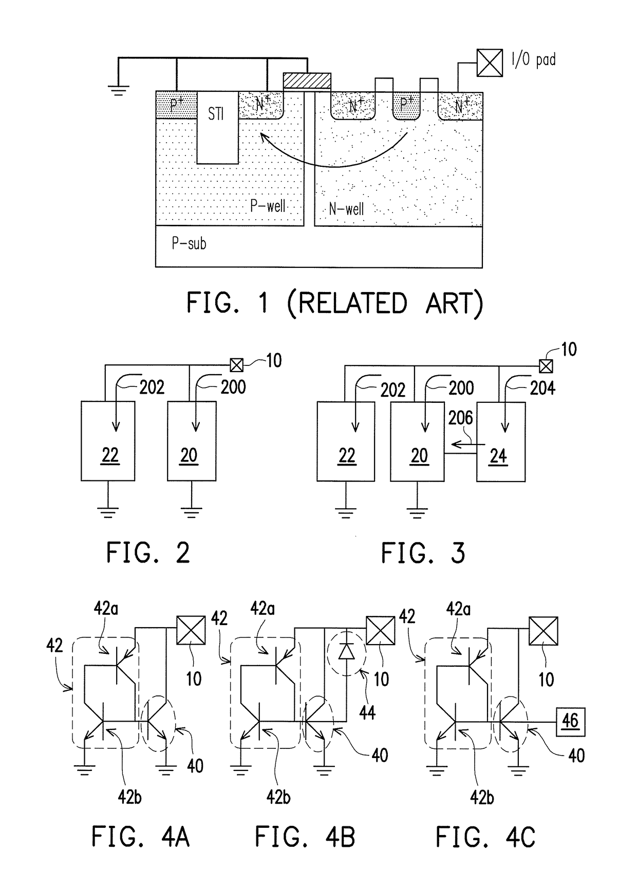
[0038]FIG. 2 illustrates a block diagram of an ESD unit according to the third aspect of this invention without a trigger element.

[0039]The ESD unit includes a first device 20, and a second device 22 coupled to the first device 20 in parallel, both of which are electrically connected to the I / O pad 10. In an ESD event, the first device 20 is turned on to flow a current 200 before the second device 22 is turned on. The second device 22 may be turned on by the turned-on first device 20 to form an ESD path 202 in the ESD event.

[0040]FIG. 3 illustrates a block diagram of an ESD unit according to the first and second aspects of this invention with a trigger element.

[0041]As compared to the ESD unit as shown in FIG. 2, the ESD unit according to the first or second aspect further includes a trigger element 24 that is als...


PUM


Abstract

An electrostatic discharge (ESD) unit is described, including a first device, and a second device coupled to the first device in parallel. In an ESD event, the first device is turned on before the second device is turned on. The second device may be turned on by the turned-on first device to form an ESD path in the ESD event.

Description

BACKGROUND OF THE INVENTION[0001]Field of Invention[0002]This invention relates to protection of an integrated circuit (IC), and particularly relates to an electrostatic discharge (ESD) unit for protecting an internal circuit from damage caused by an ESD event.[0003]Description of Related Art[0004]During an ESD event, a large current may flow through an IC and easily cause damage. The damage may occur within the device that conducts the current, and also in devices that is subjected to a significant voltage drop due to the large current flow. In order to avoid damage due to an ESD event, an ESD unit is usually added to the IC.[0005]Conventionally, a gate-grounded metal-oxide-semiconductor (GGMOS) device and a gate-driven protect circuit are used as an ESD unit, but they require a large area of the IC chip. In order to reduce the area of the ESD unit, the silicon-controlled rectifier (SCR), especially LDMOS-inserted SCR, is recently used.[0006]FIG. 1 illustrates a conventional SCR fo...

Claims


Application Information

Patent Timeline
IPC IPC(8): H01L27/02
CPCH01L27/0262H01L29/7436H01L29/861H01L29/0649H01L29/0692
Inventor HUANG, CHUNG-YUSU, KUAN-CHENGTANG, TIEN-HAOCHEN, PING-JUILAI, PO-YA
Owner UNITED MICROELECTRONICS CORP
Why Eureka
Try Eureka