Regulator circuit

Active Publication Date: 2017-05-04
SAMSUNG ELECTRONICS CO LTD
View PDF6 Cites 8 Cited by
  • Summary
  • Abstract
  • Description
  • Claims
  • Application Information

AI Technical Summary

Benefits of technology

[0012]As described above, the regulator circuit may enhance a speed at which ripple of an output voltage is reduced by providing feedback currents to nodes of the regulator a

Problems solved by technology

Recently, as the power consumption of electronic circuits increases, a size and gate capacitance of the power transistor increases as well.
This can be problematical in that the relatively large g

Method used


Image

  • Regulator circuit
  • Regulator circuit
  • Regulator circuit

Examples


Embodiment Construction

[0033]Various example embodiments will be described more fully hereinafter with reference to the accompanying drawings, in which some example embodiments are shown. The present disclosure may, however, be embodied in many different forms and should not be construed as limited to the example embodiments set forth herein. Rather, these example embodiments are provided so that this disclosure will be thorough and complete and will fully convey the scope of the present disclosure to those skilled in the art. In the drawings, the sizes and relative sizes of layers and regions may be exaggerated for clarity. Like numerals refer to like elements throughout.

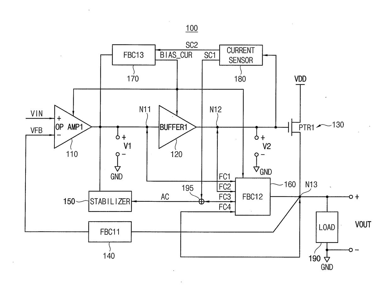
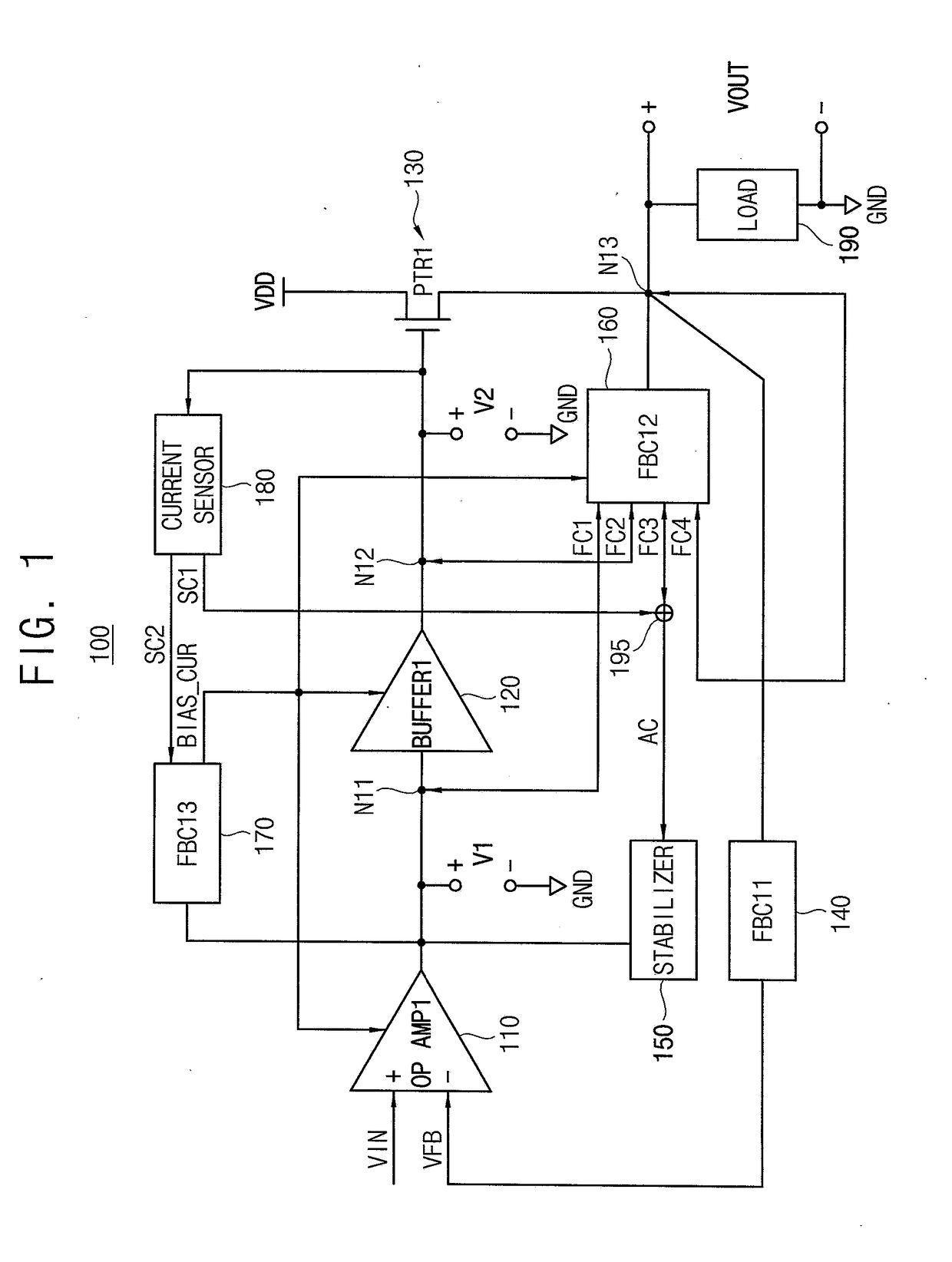
[0034]FIG. 1 is a block diagram illustrating a regulator circuit according to some example embodiments.

[0035]Referring to FIG. 1, a regulator circuit 100 includes an operational amplifier 110, a buffer 120, a power transistor 130, a first feedback circuit 140, a current sensor 180, a second feedback circuit 160, and a stabilizer 150.

[003...


PUM


Abstract

A regulator circuit includes an operational amplifier, a buffer, a power transistor, a first feedback circuit, a current sensor, and second feedback circuit. The operational amplifier drives a first node with a first voltage generated by amplifying a difference between an input voltage and a feedback voltage. The buffer drives a second node with a second voltage generated by buffering the first voltage. The power transistor has a drain receiving a supply voltage, a gate connected to the second node, and a source connected to a third node. The current sensor generates a first sensing current based on the second voltage. The second feedback circuit generates a plurality of feedback currents corresponding to a ripple of the output voltage and enhances a speed at which the ripple is reduced by providing at least one of the plurality of feedback currents to the third node.

Description

CROSS-REFERENCE TO RELATED APPLICATION[0001]This U.S. non-provisional application claims priority under 35 USC §119 to Korean Patent Application No. 10-2015-0150846, filed on Oct. 29, 2015, in the Korean Intellectual Property Office (KIPO), the disclosure of which is incorporated by reference in its entirety herein.BACKGROUND[0002]1. Technical Field[0003]Example embodiments relate generally to a regulator circuit, and more particularly to a regulator circuit capable of enhancing performance.[0004]2. Discussion of the Related Art[0005]Regulators, which are utilized as voltage sources in a wide variety of electronic circuits, are generally designed to generate a desired output voltage signal irrespective of variations in input voltage signal. The regulators typically include a power transistor which drives an output load of the electronic device.[0006]Recently, as the power consumption of electronic circuits increases, a size and gate capacitance of the power transistor increases as w...

Claims


Application Information

Patent Timeline
IPC IPC(8): H02M3/155H02M1/08H03F3/45H02M1/14
CPCH02M3/155H02M1/143H03F2203/45116H03F3/45076H02M1/08G05F1/575
Inventor DUONG, HOANG QUOCSHIN, HYUN-SEOKBAE, JUN-HYUN
Owner SAMSUNG ELECTRONICS CO LTD
Why Eureka
Try Eureka