Fluid control device

a control device and fluid technology, applied in the direction of positive displacement liquid engines, machines/engines, angiography, etc., can solve the problems of increasing power consumption, increasing power consumption, and unable to release so as to increase power consumption, increase the power consumption, and keep the pressure in the container constant

Active Publication Date: 2017-05-11
MURATA MFG CO LTD
View PDF2 Cites 2 Cited by
  • Summary
  • Abstract
  • Description
  • Claims
  • Application Information

AI Technical Summary

Benefits of technology

[0009]When keeping the pressure in the container 13 constant, the fluid control device 140 needs to continuously drive the pump 11, and this increases the power consumption. Inserting a check valve between the pump 11 and the container 13 makes it possible to keep the pressure in the container 13 constant without driving the pump 11. However, this makes it unable to release the pressure in the container 13.
[0010]When keeping the pressure in the container 13 constant, the fluid control device 150 needs to

Problems solved by technology

When keeping the pressure in the container 13 constant, the fluid control device 140 needs to continuously drive the pump 11, and this increases the power consumption.
However, this makes it unable to release the pressure in the container 13.
When keeping the pressure in the container 13 constant, the fluid control device

Method used


Image

  • Fluid control device
  • Fluid control device
  • Fluid control device

Examples


first embodiment

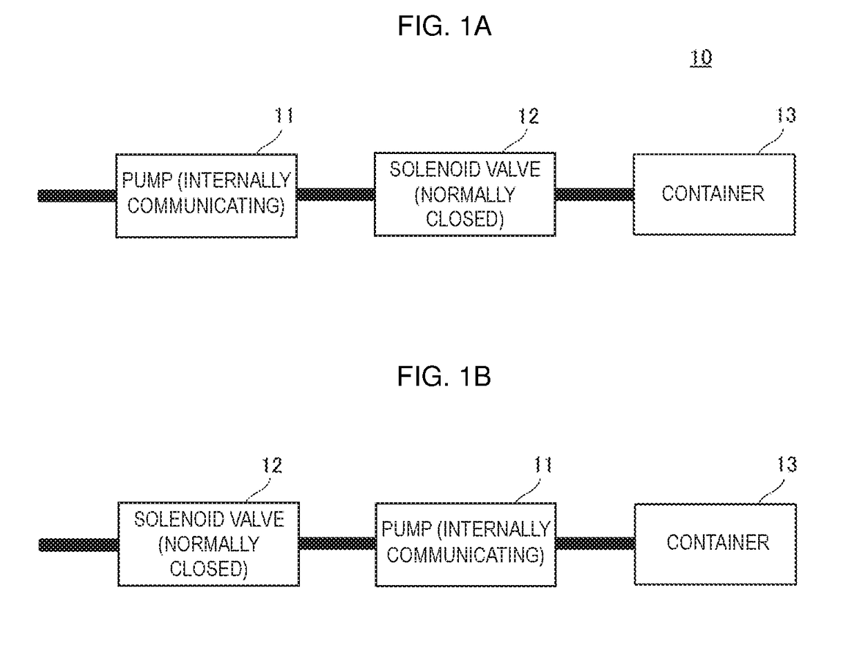
[0038]A fluid control device 10 according to a first embodiment of the present disclosure will be described. For example, the fluid control device 10 is used as a pressure massaging device that repeatedly compresses a body with an air bag. FIG. 1A is a schematic block diagram of the fluid control device 10. The fluid control device 10 includes a pump 11, a solenoid valve 12, a container 13, and a drive circuit 14 (see FIG. 3). The solenoid valve 12 corresponds to “valve” of the present disclosure. The pump 11 is connected via a tube to the solenoid valve 12. The solenoid valve 12 is connected via a tube to the container 13. The pump 11 and the solenoid valve 12 are driven by the drive circuit 14. In the fluid control device 10, the pressure in the container 13 is controlled by the operation of the pump 11. The pump 11, the solenoid valve 12, and the container 13 may be directly connected without tubes.

[0039]The pump 11 has a structure in which a suction port and a discharge port the...

second embodiment

[0059]A fluid control device according to a second embodiment of the present disclosure will be described. The fluid control device of the second embodiment is configured in the same manner as the fluid control device 10 of the first embodiment (see FIG. 1A), except for a drive circuit 54 of the second embodiment. FIG. 4 is a circuit configuration diagram of the drive circuit 54. A node between the main power source P and the node N3 is connected to the ground via resistors R3 and R4 connected in series. A node between the resistor R3 and the resistor R4 is connected to a terminal P5 of a microcontroller 57. The terminal P5 is an input terminal of an A / D converter. The other configuration of the drive circuit 54 is the same as that of the drive circuit 14.

[0060]The voltage of the main power source P divided by the resistors R3 and R4 is applied to the terminal P5 of the microcontroller 57. The microcontroller 57 converts the voltage applied to the terminal P5 into a digital value. I...

third embodiment

[0063]A fluid control device 60 according to a third embodiment of the present disclosure will be described. FIG. 5 is a schematic block diagram of the fluid control device 60. The fluid control device 60 includes the pump 61, the solenoid valve 12, the container 13, and a drive circuit 64 (see FIG. 7). The suction port of the pump 61 communicates with the outside via a flow passage in a tube. The discharge port of the pump 61 communicates with the opening of the container 13 via a flow passage in a tube. The first port of the solenoid valve 12 communicates with the flow passage in the tube positioned between the pump 61 and the container 13. The second port of the solenoid valve 12 communicates with the outside via a flow passage in a tube. That is, the pump 61 is connected to the container 13 to pressurize the inside of the container 13. The pump 61 prevents the backflow of the fluid in the non-energized state. That is, when the pump 61 is not energized, no fluid flows through the...


PUM


Abstract

A fluid control device (10) includes a container (13), a pump (11), a solenoid valve (12), and a capacitor. The pump (11) is driven by a main power source, and is capable of pressurizing or depressurizing the inside of the container (13). A suction port and a discharge port of the pump (11) internally communicate with each other. The solenoid valve (12) is connected at both ends thereof to the container (13) and the pump (11). If the voltage of the main power source is reduced or lost, the solenoid valve (12) releases pressure in the container (13) by being driven by the power stored in the capacitor or secondary battery.

Description

[0001]This is a continuation of International Application No. PCT / JP2015 / 072176 filed on Aug. 5, 2015 which claims priority from Japanese Patent Application No. 2014-163272 filed on Aug. 11, 2014. The contents of these applications are incorporated herein by reference in their entireties.FIELD OF THE DISCLOSURE[0002]The present disclosure relates to a fluid control device that controls fluid in a container.DESCRIPTION OF THE RELATED ART[0003]Examples of conventional fluid control devices include one disclosed in Patent Document 1. This fluid control device includes a cuff having a fluid bag, a pump unit configured to supply air into the fluid bag, a valve configured to open and close for discharging air from or introducing air into the fluid bag, and a CPU configured to control the drive of the pump unit and the valve. The fluid control device controls pressure in the fluid bag by driving the pump unit and the valve.[0004]FIG. 13A is a schematic block diagram of a fluid control devi...

Claims


Application Information

Patent Timeline
IPC IPC(8): A61B5/022F16K31/06F15B20/00F16K31/02A61B5/0235F04B45/047
CPCA61B5/02233A61B5/0235F04B45/047A61B2560/0214F16K31/02F16K31/06F15B20/00F04B43/0045F04B43/0081F04B43/026F04B43/046F04B49/06
Inventor HIRATA, ATSUHIKOOKAGUCHI, KENJIRO
Owner MURATA MFG CO LTD
Why Eureka
Try Eureka