Water jet device for rotary massage

a water jet device and rotary massage technology, applied in the field of sanitary industry, can solve the problems of increasing assembly costs, water jet devices may suffer from failure during use, complex mechanism, etc., and achieves the effects of improving performance, simple structure and convenient assembly

Active Publication Date: 2017-05-11
FUJIAN XIHE SANITARY WARE TECH
View PDF17 Cites 6 Cited by
  • Summary
  • Abstract
  • Description
  • Claims
  • Application Information

AI Technical Summary

Benefits of technology

[0012](2) The rotor rotates along with the impeller, and the water particles sprayed from the curved groove dashes on the inner wall of the outlet, thus forming more visualized water particles; the aforesaid effect is realized through a simple structure, thus more suitable for products with limited space.
[0013](3) The impeller fluctuates during rotation via the track assembly, further drives the water to fluctuate and changes the water flow accordingly, thus forming intermittent and dynamic water particles; compared with the driving mechanisms such as gear, worm wheel, worm screw and the like in the prior art, the track assembly is simpler, has a better performance and is easier to assemble.
[0014](4) The rotor and the impeller are either secured together or formed integrally; the fluctuation of the impeller drives the rotor to ascend and descend in the outlet, thus changing the distance between the curved grooves and the mouth of the outlet and enlarging or reducing the annular area of the water sprays accordingly for a better massage experience.
[0015](5) The diameter of the outlet is 2-12 mm, and a distance from the mouth of the outlet to the curved grooves is 2.5-8 mm; tests show that the interaction between the outlet and the track assembly in the above interval ranges ensures an optimum performance of the water sprays. Water particles from the water flow provide an optimum massage effect.
[0016](6) The invention is provided with at least one protrusion on the separating member, and the water ejection port is formed in the protrusion, thus extending the water passage and improving the water flow.
[0017](7) The water ejection port is tapered toward the seat. The tapered design of the water ejection port along with the lengthened water passage increases the flow rate.

Problems solved by technology

However, the water jet device disclosed in the publication presents a complicated mechanism involving many components, such as gear assemblies, helical worms and the like.
Due to a confined space of the water jet device, it's difficult to assemble the complicated mechanism, and this may increase the cost of assembly.
Furthermore, the water jet device may suffer from failure during use.
Because the accumulated scale forming after being used for a period of time may affect the components, and make it impossible to realize a discretionary functions switching.
Moreover, its weight is increased greatly due to the excessive number of components.
Water flow additionally adds to the weight in showering operation.
Thus, the product manufactured based on the publication does not enjoy market success.
This cannot satisfy ordinary users who desire a water jet device capable of providing a water particle spray under one pattern with better massaging effects.

Method used


Image

  • Water jet device for rotary massage
  • Water jet device for rotary massage
  • Water jet device for rotary massage

Examples


embodiment 1

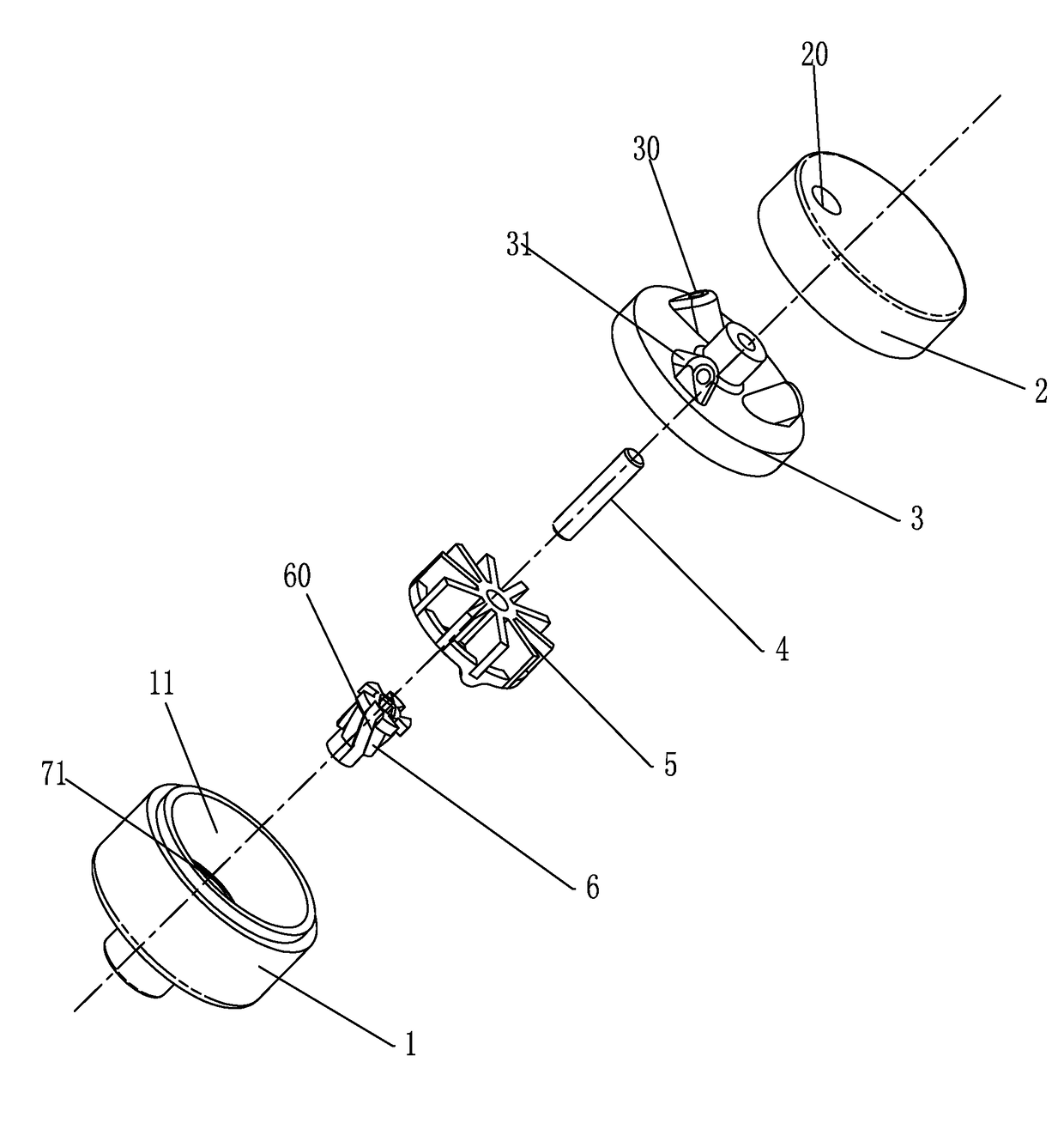
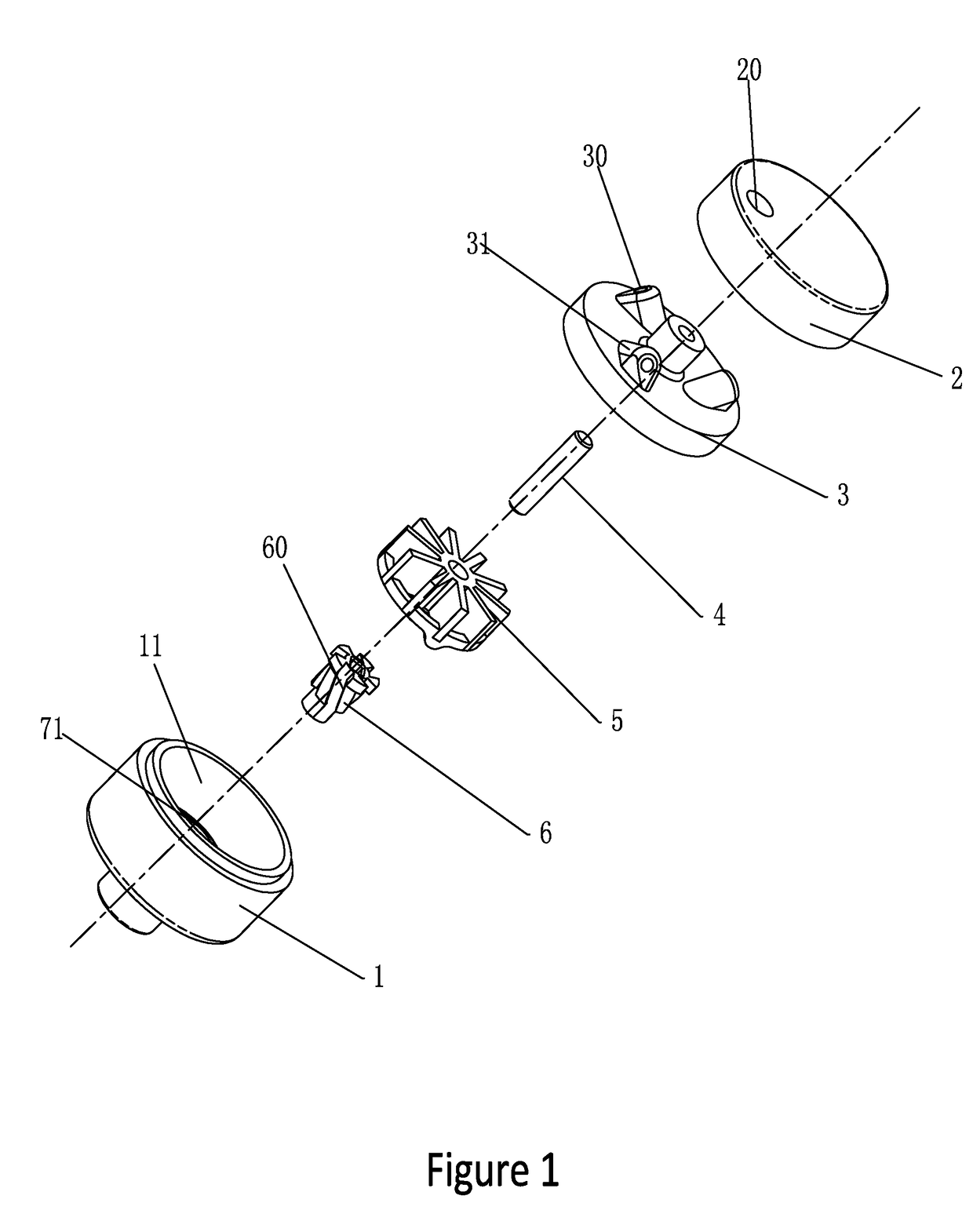
[0034]Embodiment 1 aims at providing intermittent and dynamic water sprays. The major components for the embodiment are as follows: a seat 1, a cover 2, a separating member 3, a rotary shaft 4, an impeller 5, and a rotor 6;

[0035]When in practical assembly, as shown in FIG. 1-5, firstly, the rotary shaft 4 is mounted in a center of the separating member 3; the cover 2 and the separating member 3 are welded to form a water inlet chamber;

[0036]Subsequently, the impeller 5 is sleeved on the rotary shaft 4;

[0037]Secondary, a track assembly 7 comprises an annular rail 71 formed on an inner bottom of the seat 1, and a plurality of sliders 72 formed on an underside of the impeller 5; the annular rail 71 has ascending and descending sections, and the sliders 72 are configured to move along the annular rail 71;

[0038]Thirdly, the rotor 6 is rotatably disposed in the outlet 10 of the seat 1, and curved grooves 60 formed on the outer surface of the rotor 6 are interacting with the inner wall of ...

embodiment 2

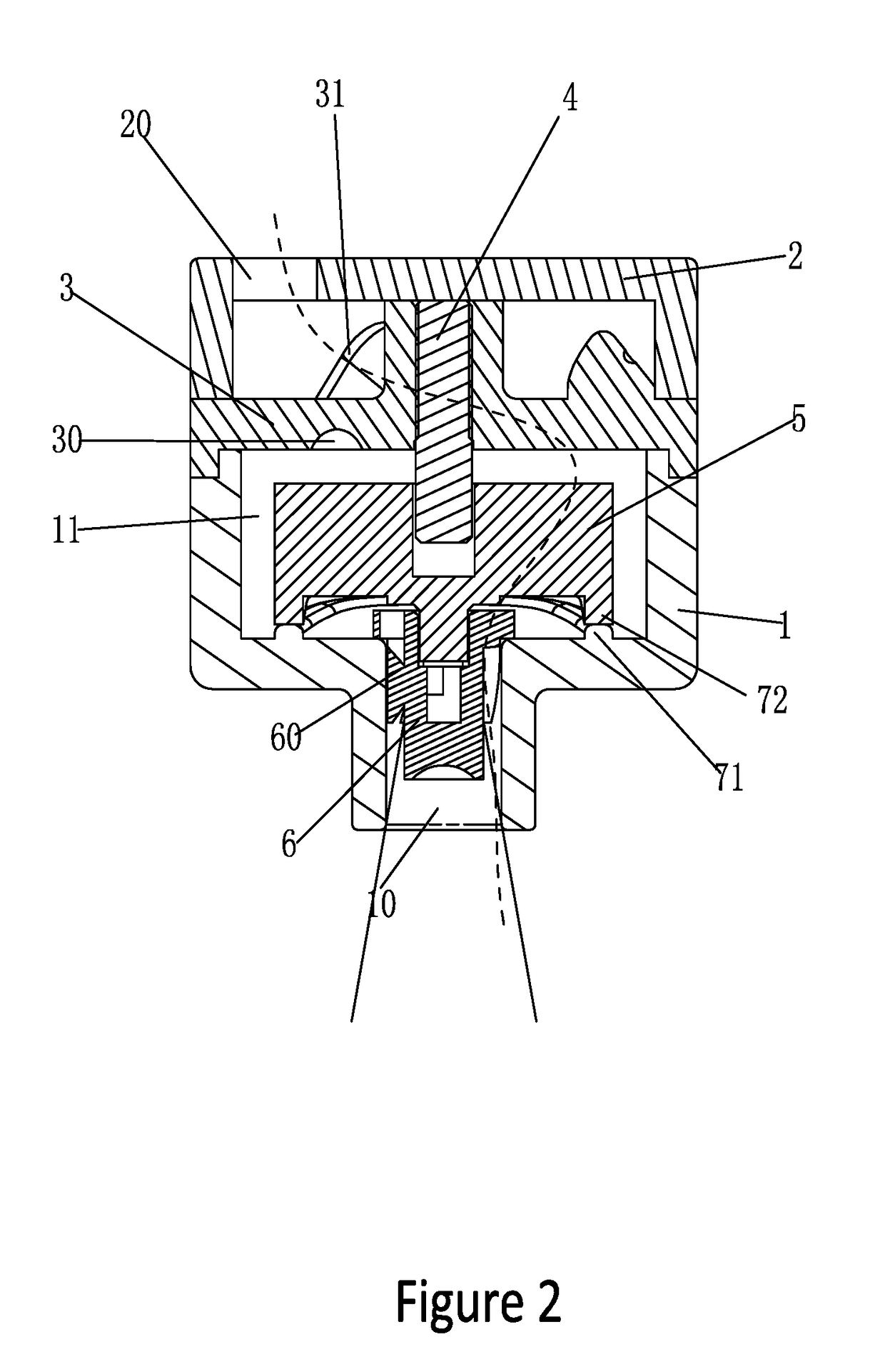
[0043]Embodiment 2 aims at providing a water spray in which the size of the water particles and the annular area changes intermittently; As shown in FIG. 1-6, the same part between Embodiment 2 and Embodiment 1 will not be repeated; the difference lies in: the impeller 5 and the rotor 6 are either secured together or formed integrally; the impeller 5 rotates about the rotary shaft (4) and fluctuates along the annular rail 71, and the rotor 6 is driven to ascend and descend, thus changing a distance between the curved grooves 60 and the mouth of the outlet 10 and enlarging or reducing the annular area of the water sprays accordingly.

[0044]Operation of the invention is described in detail below:

[0045]As shown in FIG. 9-10, the water flow direction is the same as that in Embodiment 1; the difference lies in: while the impeller 5 rotates and fluctuates, the rotor integrated to the impeller 5 also rotates and fluctuates, thus changing a distance between the curved groove 60 and the mouth...


PUM


Abstract

A water jet device for rotary massage includes a seat providing an outlet and a cavity; a cover providing an inlet; a separating member, a rotary shaft, an impeller and a rotor received in the cavity; at least one inclined water ejection port disposed on the separating member and communicating with the inlet; the impeller is mounted between the rotor and the separating member; the rotor is in the outlet, a plurality of curved grooves are formed on the periphery of the rotor; a track assembly includes an annular rail having ascending and descending sections formed on an inner bottom of the seat, and sliders formed on an underside of the impeller; water flowing through the water ejection port rotates the impeller, further drives the rotor to rotate, and the fluctuation of the impeller and the rotor drives the water fluctuates, thus form intermittent and dynamic annular water sprays.

Description

BACKGROUND OF THE INVENTION[0001]1. Field of the Invention[0002]The invention relates to the sanitary industry, in particular to a water jet device for rotary massage.[0003]2. Description of Related Art[0004]The water jet pattern of most existing water jet devices is relatively single, such as separate water particles, cylindrical water and the like. For this reason, the designers make various improvements to combine multiple water jet patterns, for example, Chinese patent publication No. CN103028499B entitled “Reciprocating Mechanism for Water Jet device” which utilizes a reciprocating mechanism to combine and switch multiple water jet patterns to achieve a better massage effect. However, the water jet device disclosed in the publication presents a complicated mechanism involving many components, such as gear assemblies, helical worms and the like. Due to a confined space of the water jet device, it's difficult to assemble the complicated mechanism, and this may increase the cost o...

Claims


Application Information

Patent Timeline
Patent Type & Authority Applications(United States)
IPC IPC(8): B05B3/04
CPCB05B3/0422A61H9/00B05B1/06B05B1/08B05B1/34A61H2201/50B05B3/04B05B3/0427B05B3/045
Inventor LIN, XIAOFALIN, XIAOSHANLIU, QIQIAODENG, XIAOQINGXU, JUN
Owner FUJIAN XIHE SANITARY WARE TECH
Why Eureka
Try Eureka