Magnetic refrigerating device

a technology of magnetic refrigerating device and magnetic field, which is applied in the direction of refrigerating machine, lighting and heating apparatus, machines using electric/magnetic effects, etc., can solve the problems of heat loss and hinder the increase of the frequency of the refrigeration cycle, and achieve the effect of increasing the cycle ra

Active Publication Date: 2017-05-11
NAT INST FOR MATERIALS SCI
View PDF2 Cites 11 Cited by
  • Summary
  • Abstract
  • Description
  • Claims
  • Application Information

AI Technical Summary

Benefits of technology

[0037]4) Rotating a component on which an AMR bed or permanent magnets are mounted easily increases the cycle rate.

Problems solved by technology

However, the conventional AMR systems have the following problems:(i) A mechanism for driving the magnetic material and the heat exchanging fluid is required, which requires high energy input;(ii) A rotation AMR needs the switching of the high- and low-heat exchanging fluids, causing a heat loss due to the mixture of the fluids during the switching, and(iii) This complex driving mechanism hinders an increase in the frequency of the refrigeration cycle.

Method used


Image

  • Magnetic refrigerating device
  • Magnetic refrigerating device
  • Magnetic refrigerating device

Examples


second embodiment

[0065]FIG. 5 is a structural diagram of the invention, showing the main structure of a device in which two horizontally opposed-type AMRs are combined. FIG. 5 shows a magnetic refrigerating device in which the horizontally opposed-type two-cylinder AMRs, which are the same as in FIG. 1 but out of phase, are combined.

[0066]In FIG. 5, AMR beds 50A and 50B each have two magnetic materials joined by a magnetic material reciprocating unit, such as a spring, and its inner structure is similar to FIG. 1 and thus is omitted in the drawing. The AMR bed 50A, which is depicted in a horizontal state in FIG. 5, is in a position overlapping permanent magnets 54a and 54b. The AMR bed 50B, which is disposed in a position intersecting the AMR bed 50A, is away from the permanent magnets 54a and 54b. The rotary shaft 55 is provided along the rotation axis of a pair of circular plates (not shown in the drawing) on which the AMR beds 50A and 50B and the magnets 54a and 54b are mounted.

[0067]Since a magn...

third embodiment

[0068]FIG. 6 is a structural diagram of the invention, showing the main structure in which four horizontally opposed-type AMRs are combined. FIG. 6, (A) is a plan view, and FIG. 6, (B) is a cross-sectional view along line A-A in FIG. 6, (A). Here, four horizontally opposed-type AMRs are combined and cold heat is further transported from low-temperature-side heat exchangers for the AMRs to coolers 68 and 70. In addition, hot heat is further transported from high-temperature-side heat exchangers for the AMRs to heat outlets 69 and 72. Rotary shaft central portions 65 and 68 of the AMRs are common components for convenience of heat exchange and drive. When viewed from the rotary shaft central portions of the AMRs, eight single-cylinder AMRs look like hub and spokes. Note that the arrow indicates the direction of the rotation of the AMR bed.

[0069]In FIG. 6, AMR beds 60A, 60B, 60C, and 60D each includes two magnetic materials joined by a magnetic material reciprocating unit, such as a sp...

fourth embodiment

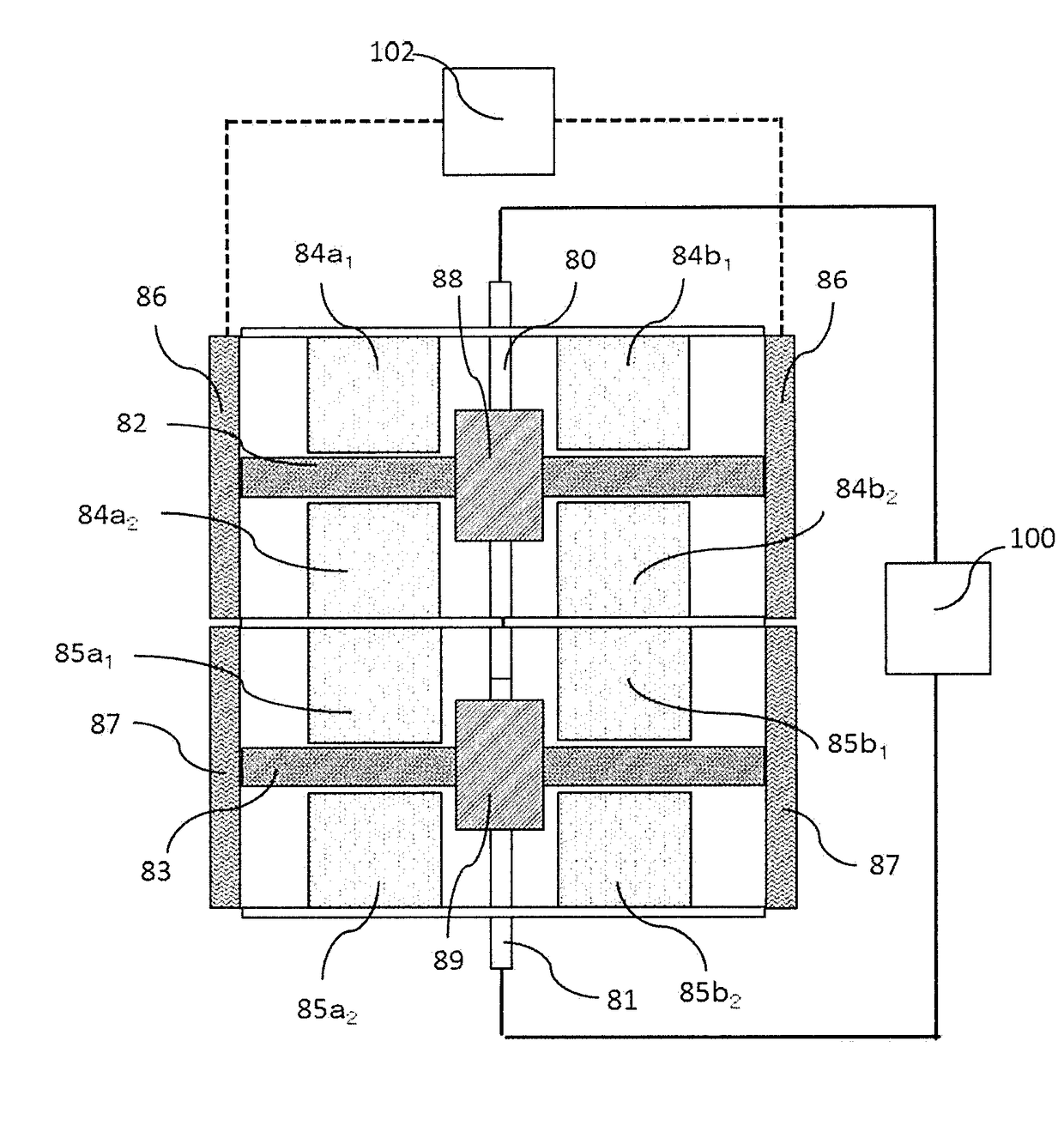
[0074]FIG. 8 is a structural diagram of the invention, showing the main structure of a device in which two horizontally opposed-type AMRs are stacked. In FIG. 8, AMR beds 82 and 83 each include two magnetic materials joined by a magnetic material reciprocating unit, such as a spring, and their inner structures are similar to FIG. 4 and thus are omitted in the drawing. Low-temperature-side heat exchangers 88 and 89 are provided in the central portions, and high-temperature-side heat exchangers 86 and 87 are provided at both ends.

[0075]The AMR bed 82, which is depicted upward in FIG. 8, is in a position overlapping permanent magnet 84a1, 84a2, 84b1, and 84b2. The AMR bed 83, which is disposed lower than the AMR bed 82, are away from the permanent magnets 85a1, 85a2, 85b1, and 85b2. Rotary shafts 80 and 81 are provided along the rotation axis of a pair of circular plates (not shown in the drawing) on which the AMR beds 82 and 83 or the permanent magnets 84a1, 84a2, 84b1, 84b2, 85a1, 85...


PUM


Abstract

Magnetic refrigerating device improves refrigerating capacity and efficiency by improving the heat exchanging method between a magnetic material and a heat exchanging fluid and devising a magnetic field applying method. The magnetic refrigerating device comprises: a cylindrical active magnetic regenerator (AMR) bed accommodating refrigerant therein; two magnetic materials disposed in the AMR bed in the axial direction, configured to be movable in the axial direction of the AMR bed, and made of material having a magnetocaloric effect; at least two permanent magnets positioned to face the two magnetic materials; a rotary shaft positioned between the two magnetic materials in the AMR bed and positioned between the at least two permanent magnets; and a magnetic rotary movement unit that rotationally moves the permanent magnets about the rotary shaft and that repeatedly moves the permanent magnets and the two magnetic materials closer together and farther apart in association with the rotational movement.

Description

TECHNICAL FIELD[0001]The present invention relates to magnetic refrigerating devices suitable for use in air conditioners, car air conditioners, refrigerators, and other devices for heating and cooling in buildings and air conditioning in rooms, particularly to magnetic refrigerating devices using a refrigerant permitted for use in refrigerant substitutes for chlorofluorocarbon and fluorine-based greenhouse effect gases which are effective for protection of the ozone layer of the earth's atmosphere.BACKGROUND ART[0002]In Japan, heating and cooling systems currently use refrigerants which are substitutes for chlorofluorocarbon, such as HFC-134a (CH2F—CF3), in order to stop serious destruction of the ozone layer due to chlorofluorocarbon. However, since these substitutes for chlorofluorocarbon give greenhouse effect 1300 times greater than that by CO2, which is defined as a greenhouse effect gas, the leakage of the currently used refrigerants to the global environment have a profound ...

Claims


Application Information

Patent Timeline
Patent Type & Authority Applications(United States)
IPC IPC(8): F25B21/00
CPCF25B21/00F25B2321/0022F25B2321/002Y02B30/00
Inventor NUMAZAWA, TAKENORI
Owner NAT INST FOR MATERIALS SCI
Why Eureka
Try Eureka