
Aerosol-generating system with self-activated electric heater

a self-activated, aerosol-generating technology, applied in the direction of ohmic-resistance heating, ohmic-resistance heating details, waterproof/air tight seals, etc., can solve the problem of insufficient accuracy of the amount of depletion determined during taping, limited power consumption, and increase in so as to free valuable space in the aerosol-generating system, increase the temperature of the heating element, and reduce costs

Active Publication Date: 2017-05-18
AKRIA CLIENT SERVICES LLC
View PDF7 Cites 23 Cited by
  • Summary
  • Abstract
  • Description
  • Claims
  • Application Information

AI Technical Summary

Benefits of technology

The invention provides a device with electronic circuitry that can activate the heater for a liquid aerosol-forming substrate without needing the user to vape. The device also monitors the depletion of the substrate, which allows for easier maintenance and reduced risk of degradation due to light exposure. The device is designed to maintain high hygiene standards.

Problems solved by technology

As a result, the precision of the amount of depletion determined during \Taping may not be sufficiently accurate.
Power consumption may be limited by infrequent use of the self-activation.
If the amount of liquid aerosol-forming substrate has decreased (e.g., if the liquid storage portion is empty or substantially empty), insufficient liquid aerosol-forming substrate may be supplied to the heater, which may result in the temperature of the heating element increasing.
If the amount of liquid aerosol-forming substrate has decreased (e.g., if the liquid storage portion is empty or substantially empty), insufficient liquid aerosol-forming substrate may be supplied to the heater.
This may result in the temperature of the heating element increasing.
This may suppress and / or avoid generation of a vapor that does not have the desired properties and / or a relatively poor experience for the adult vaper.

Method used


Image

  • Aerosol-generating system with self-activated electric heater
  • Aerosol-generating system with self-activated electric heater
  • Aerosol-generating system with self-activated electric heater

Examples


Embodiment Construction

[0075]Example embodiments will become more readily understood by reference to the following detailed description of the accompanying drawings. Example embodiments may, however, be embodied in many different forms and should not be construed as being limited to the example embodiments set forth herein. Rather, these example embodiments are provided so that this disclosure will be thorough and complete. Like reference numerals refer to like elements throughout the specification.

[0076]The terminology used herein is for the purpose of describing particular embodiments only and is not intended to be limiting. As used herein, the singular forms “a”, “an” and “the” are intended to include the plural forms as well, unless the context clearly indicates otherwise. It will be further understood that the terms “comprises,”“comprising,”“includes,” and / or “including,” when used in this specification, specify the presence of stated features, integers, steps, operations, elements, and / or components...


PUM


Abstract

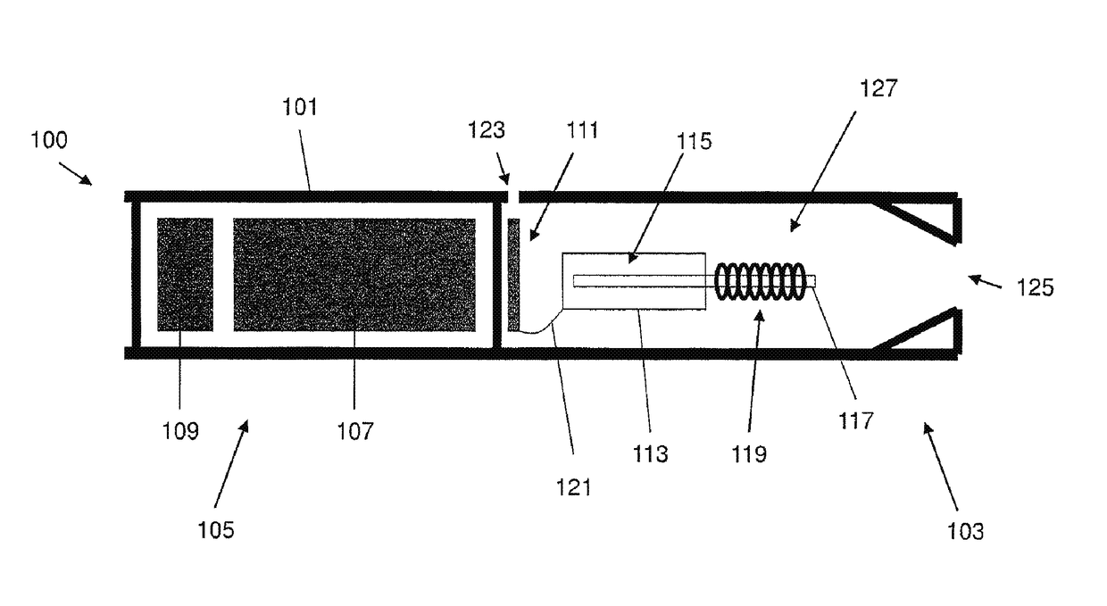
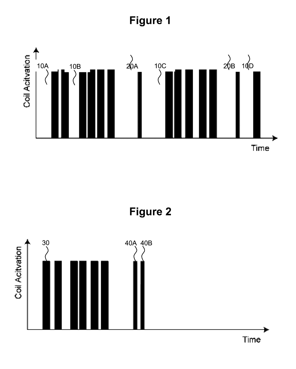
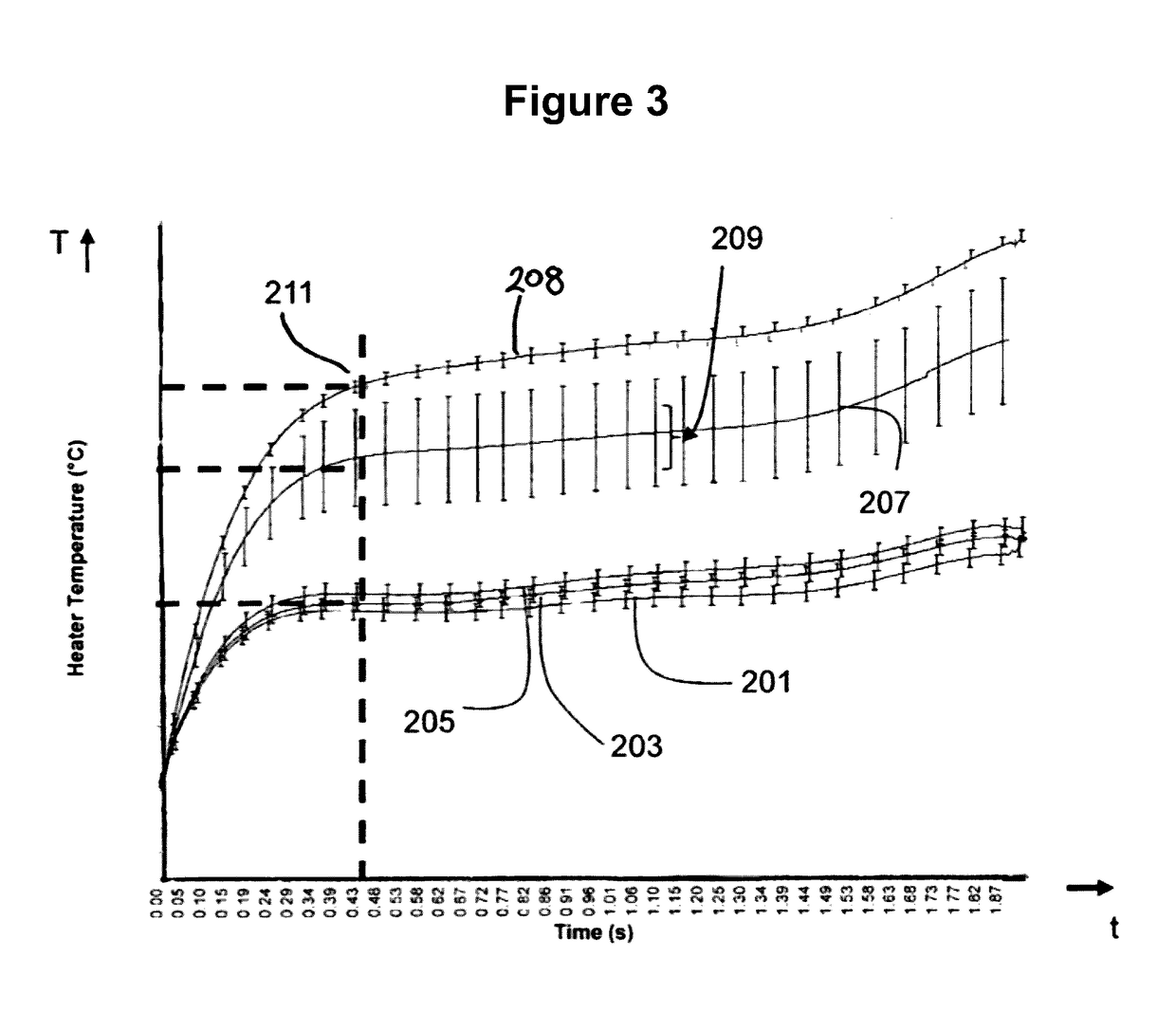
An electronic vaping device includes a liquid storage portion, an electric heater and electronic circuitry. The liquid storage portion is configured to store liquid vapor-forming substrate. The electric heater includes at least one heating element, the at least one heating element configured to heat the liquid vapor-forming substrate. The electronic circuitry is configured to self-activate the electric heater for a first time interval during a period of inactivity of the electric heater to determine depletion of the liquid vapor-forming substrate based on a relationship between a power applied to the at least one heating element and a resulting temperature change of the at least one heating element.

Description

CROSS-REFERENCE TO RELATED APPLICATIONS[0001]This application is a continuation of, and claims priority to, international application no. PCT / EP2016 / 074798, filed on Oct. 14, 2016, and further claims priority under 35 U.S.C. §119 to European Patent Application No. 15194990.6, filed Nov. 17, 2015, the entire contents of each of which are incorporated herein by reference.BACKGROUND[0002]Field[0003]One or more example embodiments relate to electrically operated aerosol-generating systems in which an aerosol-forming substrate is contained in a storage portion.[0004]Description of Related Art[0005]Related art electrically heated vaping systems (also referred to as electronic vaping or e-vaping systems) may include a liquid storage portion. The liquid storage portion includes a liquid aerosol-forming substrate, and is connected to a vaporizer comprising an electric heater, which is powered by a battery supply. When an adult vaper applies negative pressure to a mouth-end piece, the battery...

Claims


Application Information

Patent Timeline
IPC IPC(8): A24F47/00H05B1/02A24F40/10A24F40/50
CPCA24F47/008H05B2203/021H05B1/0244H05B3/04H05B3/44H05B2203/014A24F40/10A24F40/50
Inventor REEVELL, TONY
Owner AKRIA CLIENT SERVICES LLC
Learn More