
Apparatus and Method for Tracking Conveyor Belts

Active Publication Date: 2017-05-18
FLEXIBLE STEEL LACING
View PDF0 Cites 4 Cited by
  • Summary
  • Abstract
  • Description
  • Claims
  • Application Information

AI Technical Summary

Benefits of technology

The patent describes a tracking apparatus and method for urging a mistracked conveyor belt back toward a correct travel path. The apparatus includes an idler roller that engages the belt and a frame assembly for operatively mounting the idler roller to conveyor structure. The frame assembly allows the idler roller to shift in response to the mistracking of the belt. The apparatus uses a reaction force from the belt to actuate the idler roller and direct the belt back toward the correct travel path. The apparatus is bi-directional, self-energizing, and can be used with conveyor belts traveling in either direction. The apparatus is designed to overcome the limitations of previous tracking devices that only allowed for a predetermined relationship between the amount of downstream shifting of the idler roller and the tilting action of the idler roller.

Problems solved by technology

However, conveyor belts can tend to meander or mistrack laterally toward one side or the other of the rollers due to reasons such as uneven loads carried by the belt.
This upstream or downstream mounting of the sensor rollers means that the correcting mechanism is limited to use when the belt travels in a single direction.
Furthermore, this solution requires the edge of the belt to forcefully make contact with the sensor rollers, which can undesirably damage the belt.
This configuration is limited, however, because the disclosed system is not capable of tilting or raising an outer end of the roller to provide additional steering control over a mistracking belt.
However, the Parker belt tracker is limited because the tilt of the pivot axis restricts its use to belts that travel in a single direction.
In addition, the use of sensor rollers and an inclined pivot axis restricts use of the '250 publication tracking apparatus to conveyor belts that travel in a single direction.

Method used


Image

  • Apparatus and Method for Tracking Conveyor Belts
  • Apparatus and Method for Tracking Conveyor Belts
  • Apparatus and Method for Tracking Conveyor Belts

Examples


Embodiment Construction

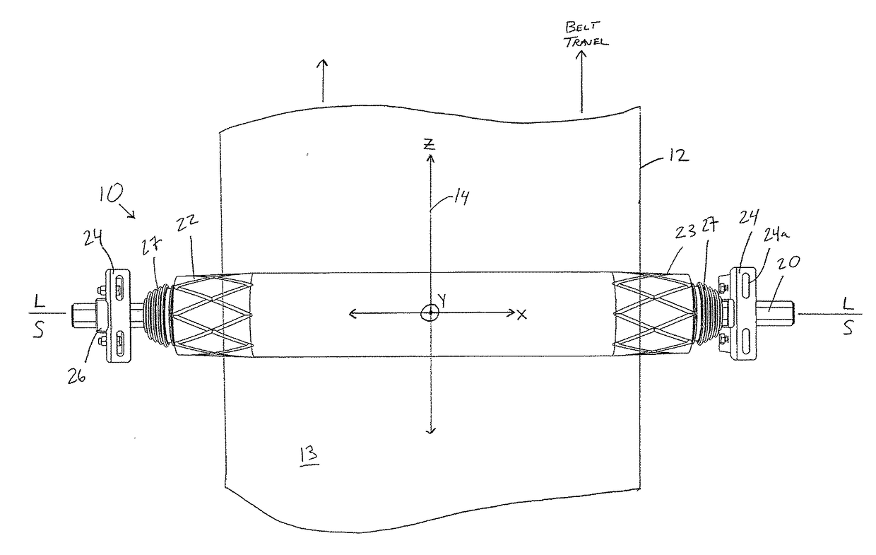
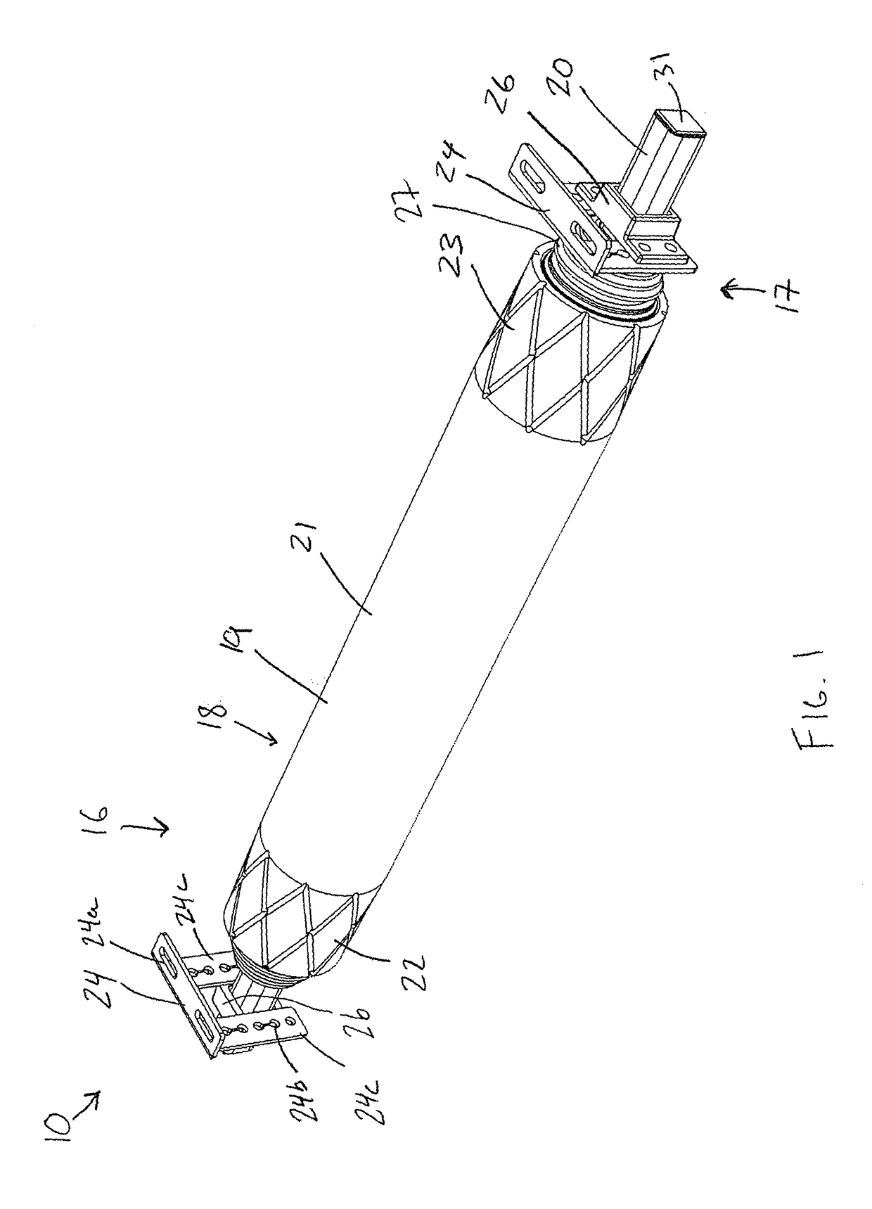
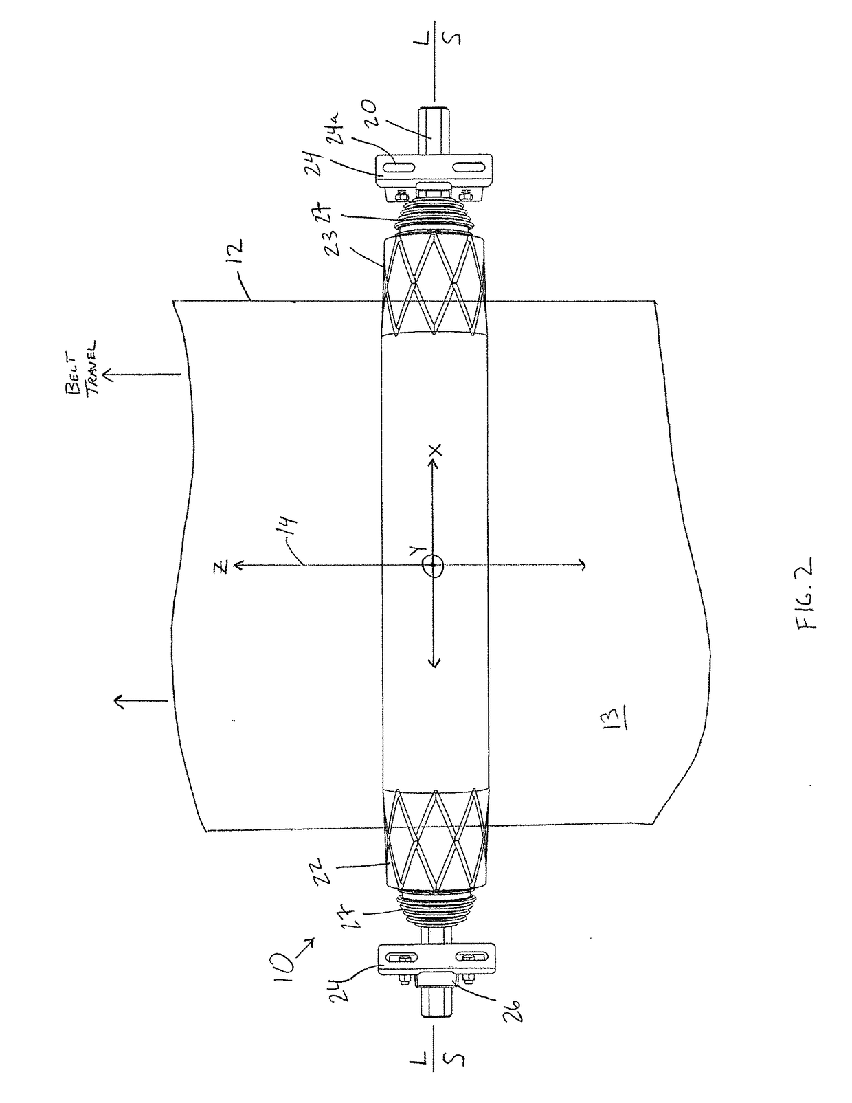
[0038]As illustrated in FIGS. 1-14, a conveyor belt tracking apparatus 10 is adapted to be used with an endless conveyor belt system positioned under a conveyor belt 12 thereof to track the belt 12 along a generally longitudinal belt travel path, the center line 14 of which is indicated at the Z axis in FIG. 2. To this end, the belt tracking apparatus 10 will be described with respect to correcting lateral misalignment of the belt 12 relative to the center line 14. The belt tracking apparatus 10 is generally symmetrical such that the structure and function of the apparatus 10 on one lateral side will be applicable to the opposite side as well.

[0039]As shown in FIGS. 1-3, the belt tracking apparatus 10 includes a roller assembly 16 having a roller 18 being mounted for rotation about its longitudinal axis L to a frame assembly 17 including an elongate central support shaft 20 extending through the roller 18 about which the roller 18 rotates. The roller 18 has a symmetrical configurati...


PUM


Abstract

A tracking apparatus and method for urging a mistracking conveyor belt towards a correct travel path are disclosed. The apparatus and method utilize downstream shifting of an end portion of an idler roller due to mistracking of the conveyor belt for steering the belt back toward its correct travel path and a reaction force from the belt due to the steering thereof for energizing a tilting action of the idler roller to raise the downstream end portion thereof. The idler roller is mounted to the conveyor structure via a frame assembly including a tilt device mounted internally within the idler roller. The roller is rotatably mounted to an inner tube, and the inner tube member is pivotally mounted to the tilt device, which in combination allow the idler roller to pivot, shift, and tilt to steer a mistracking conveyor belt in relative proportion to degree of mistracking of the belt.

Description

CROSS REFERENCE TO RELATED APPLICATION[0001]This application claims the benefit of U.S. Provisional Application No. 62 / 254,523, entitled “Apparatus and Method for Tracking Conveyor Belts”, filed Nov. 12, 2015, which is hereby incorporated by reference in its entirety.FIELD OF THE INVENTION[0002]The invention relates to tracking apparatuses and methods for tracking conveyor belts.BACKGROUND OF THE INVENTION[0003]Rollers for conveyor belts are arranged so that the conveyor belt travels thereover in a downstream belt travel direction and path. However, conveyor belts can tend to meander or mistrack laterally toward one side or the other of the rollers due to reasons such as uneven loads carried by the belt. Conveyor belt tracking devices have been developed that respond to belt mistracking to attempt to redirect the belt back to its correct travel path substantially centered on the conveyor rollers.[0004]One type of belt tracking device configured to correct a misaligned belt has senso...

Claims


Application Information

Patent Timeline
IPC IPC(8): B65G39/16
CPCB65G39/16B65G39/071B65G15/64
Inventor DEVRIES, BRETT E.
Owner FLEXIBLE STEEL LACING
Learn More