Luminescence concentrator with increased efficiency

a concentrator and efficiency technology, applied in the field ofluminescent concentrators, can solve problems such as increasing costs, and achieve the effects of increasing efficiency, increasing costs, and increasing concentrator efficiency

Active Publication Date: 2017-05-18
SIGNIFY HLDG BV
View PDF13 Cites 26 Cited by
  • Summary
  • Abstract
  • Description
  • Claims
  • Application Information

AI Technical Summary

Benefits of technology

[0006]The radiation converter element concentration is in general chosen such that substantially all radiation from the light source is absorbed over the width the radiation from the radiation source travels from a radiation input face to an opposite face. For instance, assuming a 1.2 mm wide ceramic rod comprising Lu3Al5O12:Ce (III), the Ce concentration is about 0.175% in the rod, which implies that about 98% of the blue radiation of the light source is absorbed by the cerium ion in the concentrator rod. A substantially higher concentration is considered not to add to the conversion efficiency (blue to green) and may only increase costs. It will also further shift the color point to the red. However, it has surprisingly been found that when the cerium concentration is substantially increased, the concentrator efficiency increases. It is expected that the efficiency can increase with about 10-20%.

Problems solved by technology

A substantially higher concentration is considered not to add to the conversion efficiency (blue to green) and may only increase costs.

Method used


Image

  • Luminescence concentrator with increased efficiency
  • Luminescence concentrator with increased efficiency
  • Luminescence concentrator with increased efficiency

Examples


Embodiment Construction

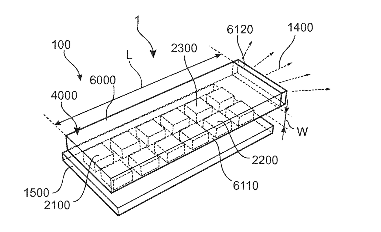
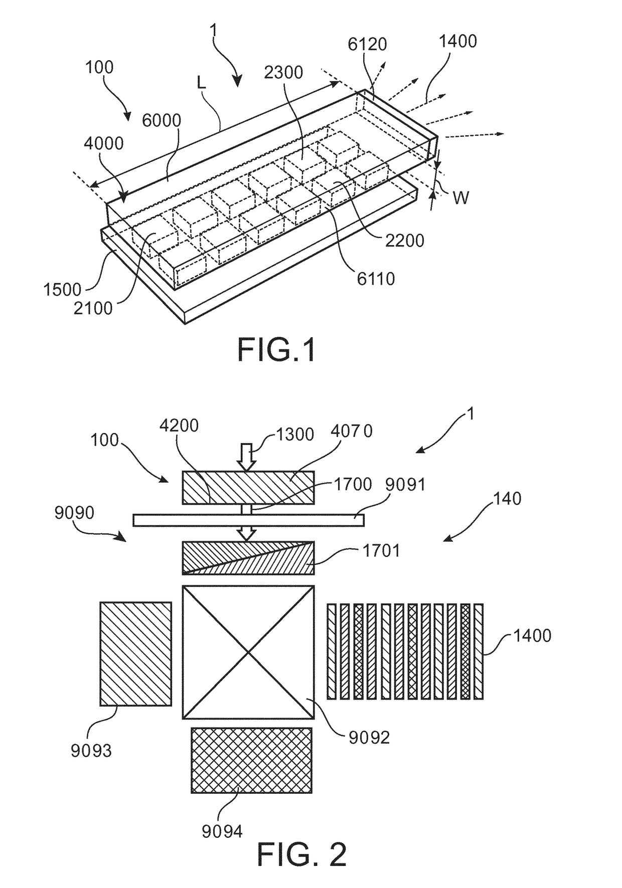
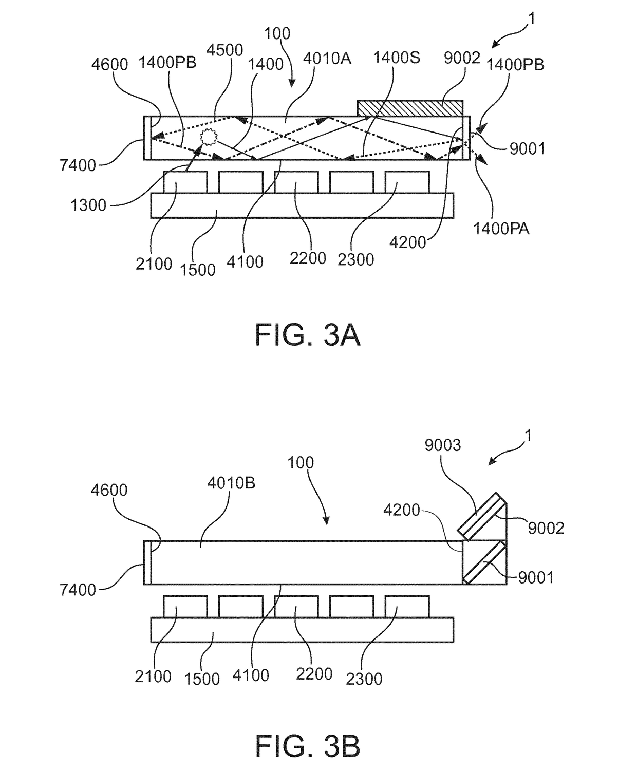
[0039]As illustrated in the figures, the sizes of layers, elements and regions are exaggerated for illustrative purposes and, thus, are provided to illustrate the general structures of embodiments of the present invention. Like reference numerals refer to like elements throughout, such that e.g. a light emitting device according to the invention is generally denoted 1, whereas different specific embodiments thereof are denoted by adding 01, 02, 03 and so forth to the general reference numeral. With regard to FIGS. 1 to 4 showing a number of features and elements which may be added to any one of the embodiments of a light emitting device according to the invention as set forth further below, generally “00” has been added to all elements except those specific to one of these Figures.

[0040]The present invention will now be described more fully hereinafter with reference to the accompanying drawings, in which currently preferred embodiments of the invention are shown. This invention may...


PUM


Abstract

The invention provides a device (1) comprising (i) a luminescent concentrator (100), the luminescent concentrator (100) comprising a waveguide (4000) having a radiation input face (4100), a radiation exit face (4200), and a width (W) defined by the radiation input face (4100) and an opposite face (4500), the waveguide (4000) comprising a radiation converter element (20) distributed in the waveguide (4000) with a converter concentration; (ii) a solid state light source (10) configured to irradiate the radiation input face (4100) of the waveguide (4000) with solid state light source radiation (11); wherein the radiation converter element (20) is configured to absorb at least part of the light source radiation (11) and to convert into radiation converter element radiation (21), and wherein the converter concentration is at least three times higher than necessary to absorb 98% of the light source radiation (11) over the width (W) of the waveguide (4000).

Description

FIELD OF THE INVENTION[0001]The invention relates to a luminescent concentrator. The invention also relates to applications thereof, such as a digital projector unit comprising such luminescent concentrator, or an automotive lighting unit comprising such luminescent concentrator.BACKGROUND OF THE INVENTION[0002]Luminescence concentrators are known in the art. U.S. Pat. No. 7,982,229, for instance, describes amongst others a light emitting device comprising at least one LED which emits light in the wavelength range of ≧220 nm to ≦550 nm and at least one conversion structure placed towards the at least one LED without optical contact, which converts at least partly the light from the at least one LED to light in the wavelength range of ≧300 nm to ≦1000 nm, characterized in that the at least one conversion structure has a refractive index n of ≧1.5 and ≦3 and the ratio A:E is ≧2:1 and ≦50000:1, where A and E are defined as follows: the at least one conversion structure comprises at lea...

Claims


Application Information

Patent Timeline
Patent Type & Authority Applications(United States)
IPC IPC(8): F21V8/00G02B1/02G03B21/20F21S8/10
CPCG02B6/0068G02B6/0075G02B6/0085G02B6/0056G03B21/204F21S48/1241F21S48/114G02B1/02G02B6/0035F21Y2101/00G02B6/0003G02B6/0073G02B6/0076H01L33/501H01L33/504H01L33/505H04N9/3158F21V13/14F21Y2115/10F21S41/13F21S41/135F21S41/153F21S41/24F21S41/285F21V9/30
Inventor PEETERS, MARTINUS PETRUS JOSEPH
Owner SIGNIFY HLDG BV
Why Eureka
Try Eureka