Vibration type magnetic separator for mine

A vibratory and magnetic separator technology, applied in magnetic separation, chemical instruments and methods, solid separation, etc., can solve the problems of low recovery rate and low grade of concentrate

Active Publication Date: 2016-02-24
盐城市锐金磨料磨具有限公司
View PDF7 Cites 10 Cited by
  • Summary
  • Abstract
  • Description
  • Claims
  • Application Information

AI Technical Summary

Problems solved by technology

[0004] The purpose of the present invention is to solve the above-mentioned problems and provide a simple and compact vibrating magnetic separator for mines with a small footprint. The vibrating plate and magnetic separation equipment are combined to expose the magnetic materials in the minerals. It is absorbed by the magnetic system on the surface, which greatly improves the absorption rate of magnetic materials in minerals. It mainly solves the problems of low recovery rate of some weak magnetic ore particles and low concentrate grade in existing magnetic separators, improves the beneficiation efficiency, and solves the problem of magnetic The non-magnetic parts of the separator are magnetized, and at the same time improve the adaptability of the magnetic separator and enhance the corrosion resistance of the magnetic separator

Method used


Image

  • Vibration type magnetic separator for mine
  • Vibration type magnetic separator for mine

Examples


Embodiment 1

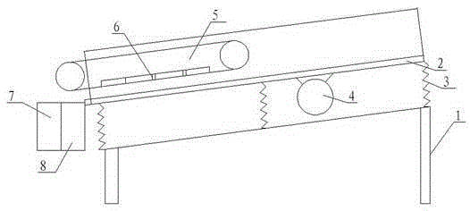
[0037] Such as figure 1 As shown, the vibrating magnetic separator for mines of the present invention includes a frame 1, and the frame 1 is provided with a vibrating plate 2 arranged obliquely, and the vibrating plate 2 is arranged inclined at 30°-45°, preferably Arranged at an angle of 43°, the vibrating plate 2 is arranged on the frame 1 through the vibrating spring 3, and the bottom surface of the vibrating plate 2 is provided with a vibrator 4; above the lower end of the vibrating plate 2, a magnetic separator is provided. Equipment 5, the end of the vibration plate 2 is provided with a non-magnetic ore port 7 and a magnetic ore port 8, wherein the magnetic ore port 8 is aligned with the ore throwing place of the magnetic separation equipment 5. Wherein said magnetic separation device 5 comprises a pair of rollers, a conveyor belt and a magnetic system 6, said conveyor belt is driven around the pair of rollers, said transmission belt is relatively parallel to the highest ...

Embodiment 2

[0050] This embodiment is the same as Embodiment 1, except that the components of the non-magnetic stainless steel of the vibration plate 2 are calculated by weight percentage (the following % all represent weight percentages): carbon is 0.15%, nickel is 5%, Chromium is 8%, manganese is 8%, silicon is 4%, niobium is 0.65%, vanadium is 0.47%, molybdenum is 1.2%, titanium is 3%, rare earth is 0.33%, and the total amount of phosphorus and sulfur does not exceed 0.035%. The balance is iron and its unavoidable impurities.

[0051] Above-mentioned non-magnetic stainless steel is made through the following steps:

[0052] Step 1. Use an intermediate frequency induction furnace for melting, put the raw iron into the converter for heating and melting, after the raw iron is completely melted, adjust the temperature of the molten pool so that the temperature of the molten pool is controlled at about 1550°C, and then add a decarburizer into the molten pool , desulfurizer, deoxidizer, dec...

Embodiment 3

[0062] This embodiment is the same as Embodiments 1 and 2, except that the components of the non-magnetic stainless steel of the vibrating plate 2 are calculated by weight percentage (the following % all represent weight percentages): carbon is 0.21%, nickel is 3 %, chromium is 13%, manganese is 11%, silicon is 5%, niobium is 0.48%, vanadium is 0.13%, molybdenum is 1.7%, titanium is 4%, rare earth is 0.27%, and the total amount of phosphorus and sulfur does not exceed 0.035 %, the balance is iron and its unavoidable impurities.

[0063] The preparation method of above-mentioned nonmagnetic stainless steel comprises the following steps:

[0064] Step 1. Use an intermediate frequency induction furnace for melting, put the raw iron into the converter for heating and melting, after the raw iron is completely melted, adjust the temperature of the molten pool so that the temperature of the molten pool is controlled at about 1550°C, and then add a decarburizer into the molten pool ,...


PUM

PropertyMeasurementUnit
thicknessaaaaaaaaaa
thicknessaaaaaaaaaa

Abstract

The invention discloses a vibration type magnetic separator for a mine, and belongs to the technical field of mine machinery. The vibration type magnetic separator for the mine comprises a frame, wherein the frame is provided with an inclined vibration flowing plate; the vibration flowing plate is arranged on the frame through a vibration spring; a vibration exciter is arranged on the bottom surface of the vibration flowing plate; magnetic separation equipment is arranged above the lower end of the vibration flowing plate; a nonmagnetic ore port and a magnetic ore port are formed in the tail end of the vibration flowing plate; and the magnetic ore port is aligned to an ore polishing place of the magnetic separation equipment. The vibration type magnetic separator for the mine is simple and compact, and is small in floor area; and the vibration plate and the magnetic separation equipment are combined, so that a magnetic material in a mineral is exposed on the surface and absorbed by a magnetic system, and the absorptivity of the magnetic material in the mineral is greatly improved.

Description

technical field [0001] The invention relates to the technical field of mining equipment, in particular to magnetic separation equipment for mining. Background technique [0002] At present, the magnetic separators used to process magnetite-type iron ore are generally drum-type magnetic separators. Because the drum of the drum-type magnetic separator needs to rotate continuously, and the magnetic system in the drum must remain fixed, Therefore, there is a gap between the magnetic system and the inner wall of the drum, which weakens the magnetic field strength of the outer wall of the drum, so that the magnetic energy of the magnetic system cannot be fully utilized. Magnetic separators, especially strong magnetic separators, are seldom used in ilmenite beneficiation operations. Generally, only weak magnetic ones are used for iron removal of ilmenite ore materials, while sand-titanium ore is beneficiated with spiral rollers, which has poor adaptability and low recovery rate. A...

Claims


Application Information

Patent Timeline
Patent Type & Authority Applications(China)
IPC IPC(8): B03C1/16C22C38/58C22C33/04B23P15/00
CPCB03C1/16B23P15/00C22C33/04C22C38/005C22C38/44C22C38/46C22C38/48C22C38/50C22C38/58
Inventor 卢晔
Owner 盐城市锐金磨料磨具有限公司
Why Eureka
Try Eureka