Apparatus, Systems and Methods for Ground Plane Extension

a technology of apparatus and systems, applied in electrical apparatus, instruments, measurement devices, etc., can solve the problems of inability to properly image disparities on planes, inability to accurately image areas of prior art, and insufficient accuracy of these prior art rendered spaces for certain applications

Inactive Publication Date: 2017-05-18
PRAXIK LLC
View PDF4 Cites 21 Cited by
  • Summary
  • Abstract
  • Description
  • Claims
  • Application Information

AI Technical Summary

Benefits of technology

[0009]Discussed herein are various embodiments of a vision system utilized for imaging in depth cameras. The presently-disclosed vision system improves upon this prior art by retaining color information and extending a known plane to render the interpose depth information into a relatively static color image or as part of live AR. The disclosed vision system accordingly provides a platform for user interactivity and affords the opportunity to utilize depth information that is intrinsic to the color image or video to refine the depth projections, such as by extending the ground plane.
[0011]The vision system disclosed herein is capable of using discovered planes, such as the ground plane, to extrapolate the depth to further objects. In certain embodiments of the vision system, depth samples are mapped onto a vision camera's native coordinate system or placed on an arbitrary coordinate system and aligned to the depth camera. In further embodiments, the depth camera can make measurements of structures known to be perpendicular or parallel to the ground plane exceeding a distance of 8 meters. In certain embodiments, the vision system is configured to automatically remove objects such as furniture from an image and replace the removed object with a plane or planes of visually plausible vision and texture. In some embodiments, the system can accurately measure an extracted ground plane to create a floor plan for a room based on wall distances, as described below. Variously, the system can detect defects in walls, floors, ceilings, or other structures. Further, in some implementations the system can accurately image areas in bright sunlight.

Problems solved by technology

Beyond 8 meters, the depth samples from these depth cameras become too sparse to support various applications, such as adding measurements or accurately placing or moving 3D objects in the rendered space.
For instance, even at 3-4 meters, the accuracy of these prior art rendered spaces is inadequate for certain applications such as construction tasks requiring eighth-inch accuracy.
Further, current applications are unable to properly image disparities on planes caused by certain irregularities or objects, such as furniture, divots, or corners.
Further still, current depth cameras are unable to properly image locations that are hit by sunlight because of infrared interference created by the sun.
Finally, because current depth cameras are unable to match the imaging range of color cameras, users are not able to use color images as an interface and must instead navigate less intuitive data representations such as point clouds.
However, these systems are not optimal when utilizing the depth data in a color photo or video or as part of a live augmented reality (“AR”) video stream.
Further, even for closer objects in a color photo, the depth samples may not be accurate or dense enough to make accurate measurements.
In these instances, utilizing depth data—such as by making measurements, placing objects, and the like—cannot be employed at all or have limited spatial resolution or accuracy, which may be inadequate for many applications.
However, this effectively discards much of the data in the color image and does not provide an intuitive user experience.
Additionally, it is difficult and / or expensive to use a depth camera in large spaces at all, as it must be done by way of a laser scanner.

Method used


Image

  • Apparatus, Systems and Methods for Ground Plane Extension
  • Apparatus, Systems and Methods for Ground Plane Extension
  • Apparatus, Systems and Methods for Ground Plane Extension

Examples


Embodiment Construction

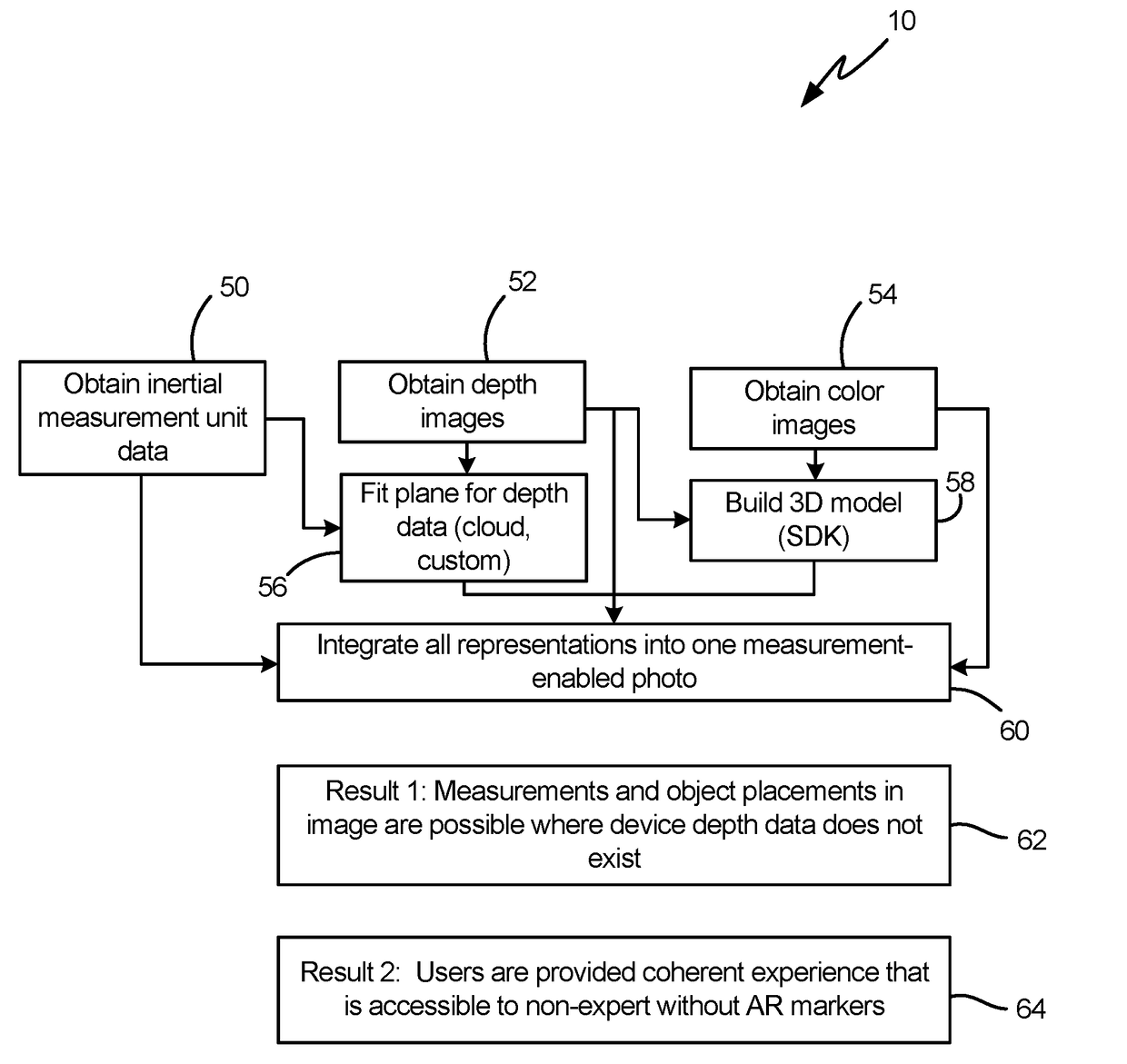
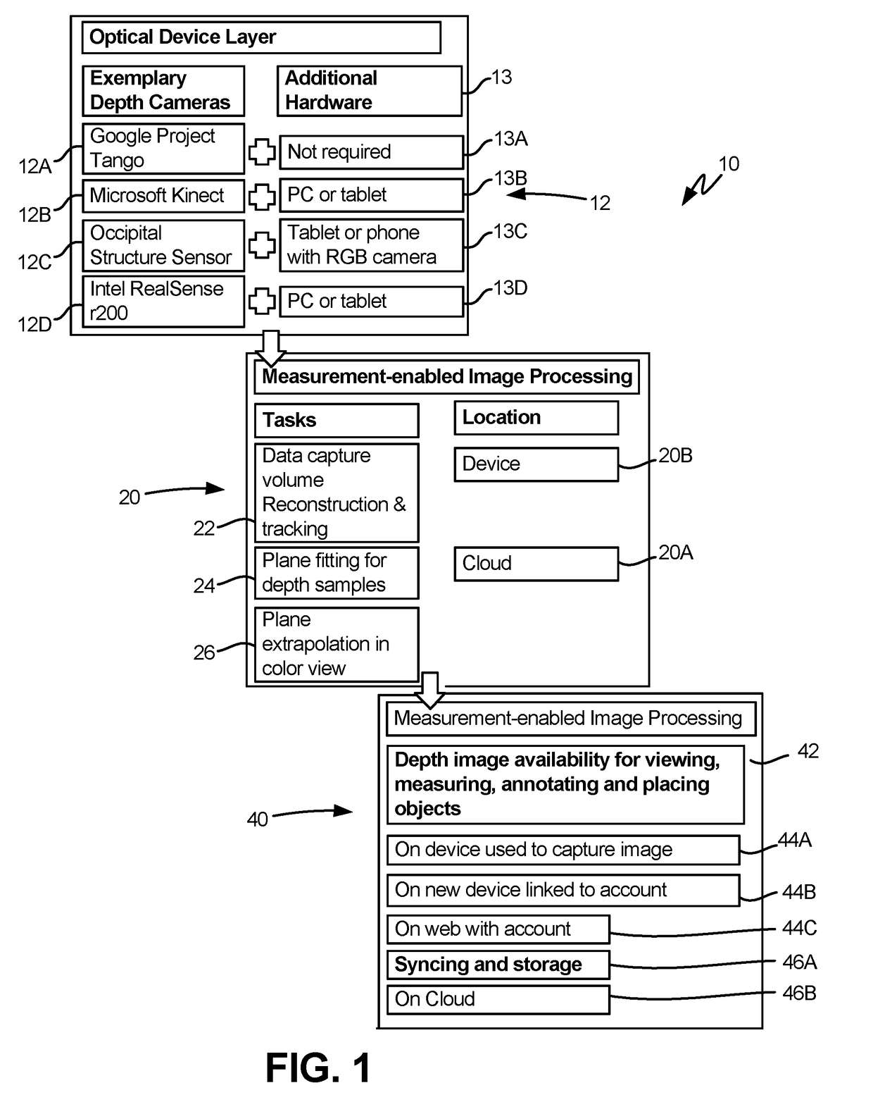
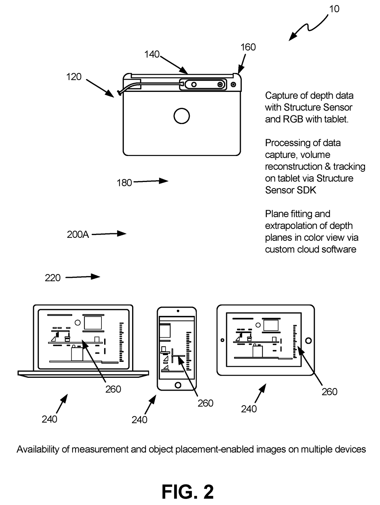
[0034]The disclosed devices, systems and methods relate to a vision system 10 capable of extending a plane in a field of view by making use of a combination of depth information and color, or “visual” images to accurately render depth into the plane. As is shown in FIGS. 1-2, the vision system 10 embodiments generally comprise a handheld (or mounted) optical device (box 12 in FIG. 1), a measurement-enabled image processing system, or “processing system” (box 20), and an application, interaction and storage platform, or “application” (box 40). In various embodiments, these aspects can be distributed across one or more physical locations, such as on a tablet, cellular phone, cloud server, desktop or laptop computer and the like. Optionally, the processing device, by executing the logic or algorithm, may be further configured to perform additional operations. While several embodiments are described in detail herein, further embodiments and configurations are possible.

[0035]FIGS. 1-10 d...


PUM


Abstract

The disclosed apparatus, systems and methods relate to a vision system which improves the performance of depth cameras in communication with vision cameras and their ability to image and analyze surroundings.

Description

CROSS-REFERENCE TO RELATED APPLICATION(S)[0001]This application claims priority to U.S. Provisional Application No. 62 / 244,651 filed Oct. 21, 2015 and entitled “Apparatus, Systems and Methods for Ground Plane Extension,” which is hereby incorporated by reference in its entirety under 35 U.S.C. §119(e).TECHNICAL FIELD[0002]The disclosure relates to a system and method for improving the ability of depth cameras and vision cameras to resolve both proximal and distal objects rendered in the field of view of a camera or cameras, including on a still image.BACKGROUND[0003]The disclosure relates to a vision system for improved depth cameras, and more specifically, to a vision system, which improves the ability of depth cameras to image and model, objects rendered in the field of view at greater distances, with greater sensitivity to discrepancies of planes, and with greater ability to image in sunny environments.[0004]Currently, depth cameras utilizing active infrared (“IR”) technology, in...

Claims


Application Information

Patent Timeline
Patent Type & Authority Applications(United States)
IPC IPC(8): H04N13/02G06T19/00
CPCH04N13/0207H04N2013/0081H04N13/0275G06T19/006G01C11/04G01B11/2545H04N13/271H04N13/207H04N13/275
Inventor SHORS, LUKEBRYDEN, AARON
Owner PRAXIK LLC
Why Eureka
Try Eureka