Pressure Compensating Emitter Having Very Low Activation Pressure and Large Operating Range

Active Publication Date: 2017-05-25
MASSACHUSETTS INST OF TECH
View PDF3 Cites 18 Cited by
  • Summary
  • Abstract
  • Description
  • Claims
  • Application Information

AI Technical Summary

Benefits of technology

[0009]The pressure-compensating emitter according to the invention includes an inlet connected to a source of pressurized water and an orifice in fluid communication with the inlet and extending into a channel including a raised land surrounding an outlet. A compliant membrane is positioned above the land in the chamber wherein the pressurized wa

Problems solved by technology

As water in drip irrigation systems travels through a pipe network including a sub main and lateral pipes from a water source out to a field, there is a continuous pressure loss due to frictional forces that develop between the pipe and flowing water.
Other factors such as elevation can also result in water pressure variation.
If non-pressure compensating emitters are used, the emitters subject to higher pressures will emit

Method used


Image

  • Pressure Compensating Emitter Having Very Low Activation Pressure and Large Operating Range
  • Pressure Compensating Emitter Having Very Low Activation Pressure and Large Operating Range
  • Pressure Compensating Emitter Having Very Low Activation Pressure and Large Operating Range

Examples


Embodiment Construction

[0032]The pressure-compensating emitters of the invention utilize the same principles exhibited by other current pressure-compensating emitters. A compliant diaphragm sits on top of a pressure chamber and the flow path deforms under pressure and changes the cross section and length of the flow path resulting in approximate linear increases in resistances for increases in pressure resulting in a constant flow rate over a fluctuation and / or variation in pressure.

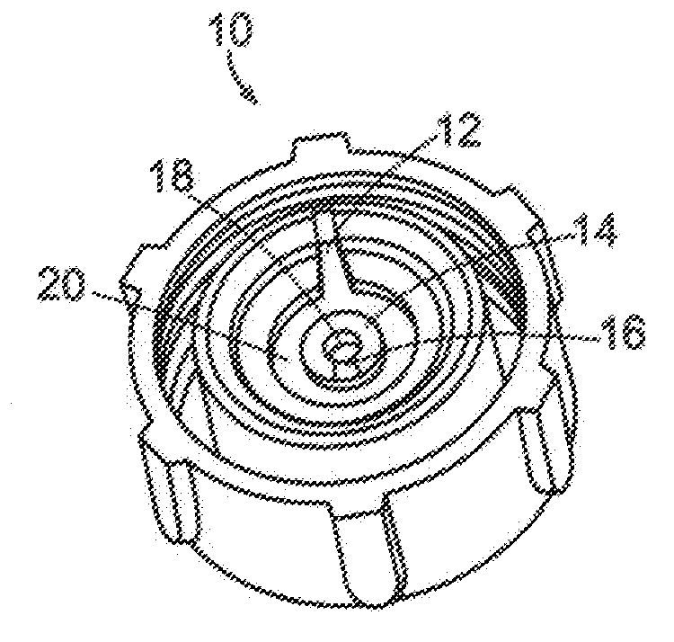
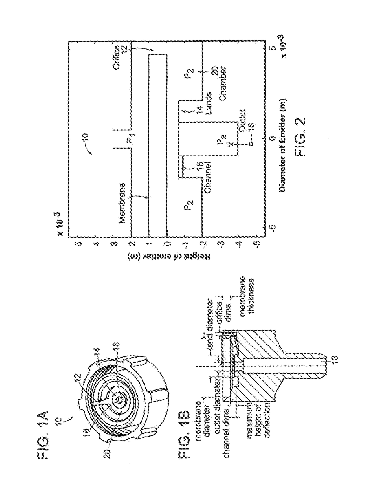
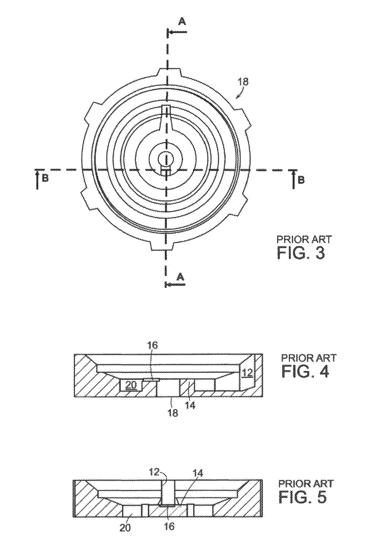
[0033]With reference first to FIGS. 1a and 1b, a typical emitter 10 includes an orifice 12, land 14, a channel 16, an outlet 18 and a chamber 20. As will be seen, the dimensions of these features affect activation pressure. The emitter 10 typically consists of tubular structures made from hard plastic usually injection molded. The compliant membrane within it deforms and leads to pressure-compensating behavior. FIGS. 1a and 1b illustrate the parameters that influence the emitter 10 performance. The parameters of interest with ...


PUM


Abstract

Pressure-compensating emitter. The emitter includes an inlet connected to a source of pressurized water and an orifice in fluid communication with the inlet and extending into a channel including a raised land surrounding an outlet. A compliant membrane is positioned above the land in the chamber wherein pressurized water will cause the membrane to deform into contact with the land to alter flow through the outlet so as to provide a constant flow rate. Parameters of the emitter are selected so that the emitter has a large operating range and an activation pressure of 0.15 bar or below.

Description

[0001]This application claims priority to provisional application Ser. No. 62 / 258,067 filed on Nov. 20, 2015, the contents of which are incorporated herein by reference.BACKGROUND OF THE INVENTION[0002]This invention relates to irrigation emitters and more particularly to an irrigation emitter providing pressure compensation so that flow rate remains substantially constant as input pressure varies.[0003]Drip irrigation systems are used to deliver water and / or nutrients directly to the root zone of a plant. In use, an online emitter is inserted into the water lateral lines. The emitter thus acts as a point source for water. Because water is delivered in a controlled way, it is possible to irrigate with substantially less water as compared to conventional water delivery systems including sprinklers and flooding methods. Drip irrigation systems also experience less water percolation, surface run off or evaporation, all saving water. Other advantages are fewer weeds as water is applied ...

Claims


Application Information

Patent Timeline
IPC IPC(8): A01G25/02G05D16/06
CPCG05D16/0647A01G25/023Y02P60/21A01G25/02B05B1/3006
Inventor SHAMSHERY, PULKITWINTER, AMOS G.
Owner MASSACHUSETTS INST OF TECH
Why Eureka
Try Eureka