Method and System for Autofocus Radar Imaging

Active Publication Date: 2017-05-25
MITSUBISHI ELECTRIC RES LAB INC
View PDF0 Cites 15 Cited by
  • Summary
  • Abstract
  • Description
  • Claims
  • Application Information

AI Technical Summary

Benefits of technology

[0008]The embodiments of the invention provide a method and system for mono-static radar imaging with a radar system with unknown position perturbations up to several wavelengths. In order to improve the imaging performance, we provide a data-driven autofocus (AF) method to concurrently perform focused imaging and estimate unknown ant

Problems solved by technology

Compared to other prior art AF methods, which typically exhibit poor performance with large position errors, this AF method significantly improves the imaging p

Method used


Image

  • Method and System for Autofocus Radar Imaging
  • Method and System for Autofocus Radar Imaging
  • Method and System for Autofocus Radar Imaging

Examples


Example

[0013]The embodiments of our invention provide a method and system for mono-static radar imaging with a radar system with unknown position perturbations up to several wavelengths.

[0014]Data Acquisition Model and Inverse Imaging

[0015]Data Acquisition Model

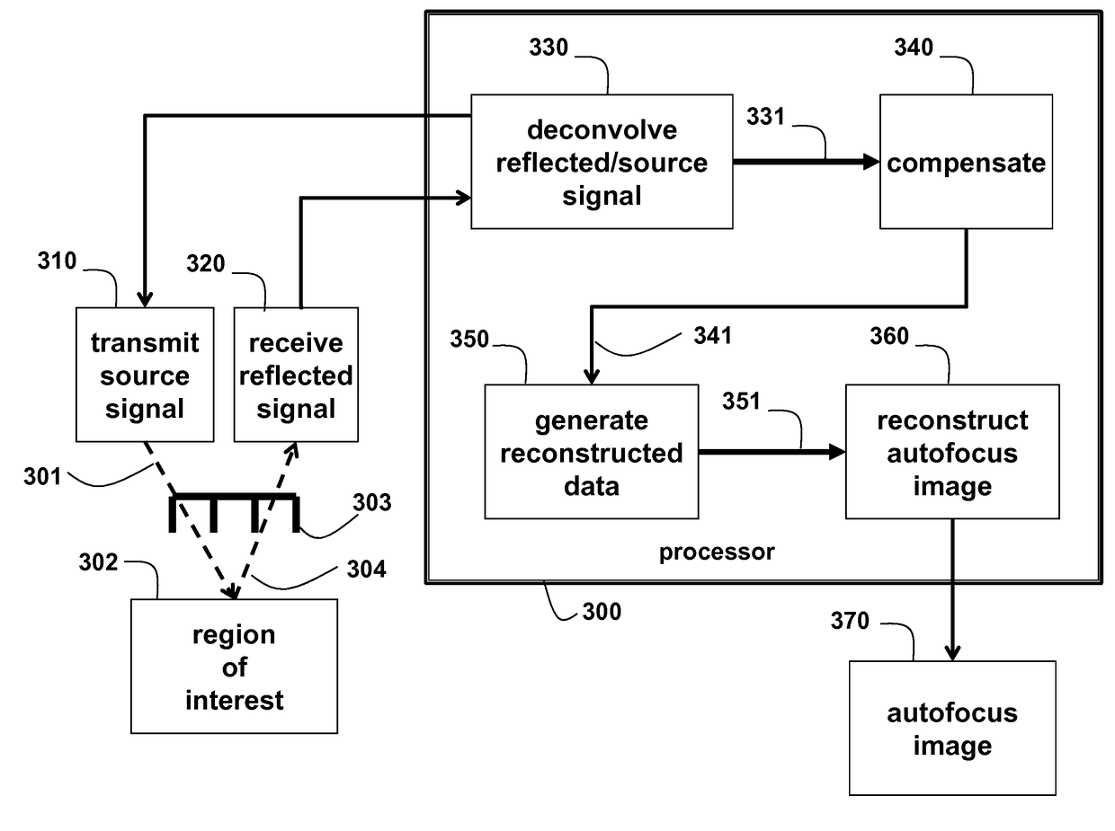
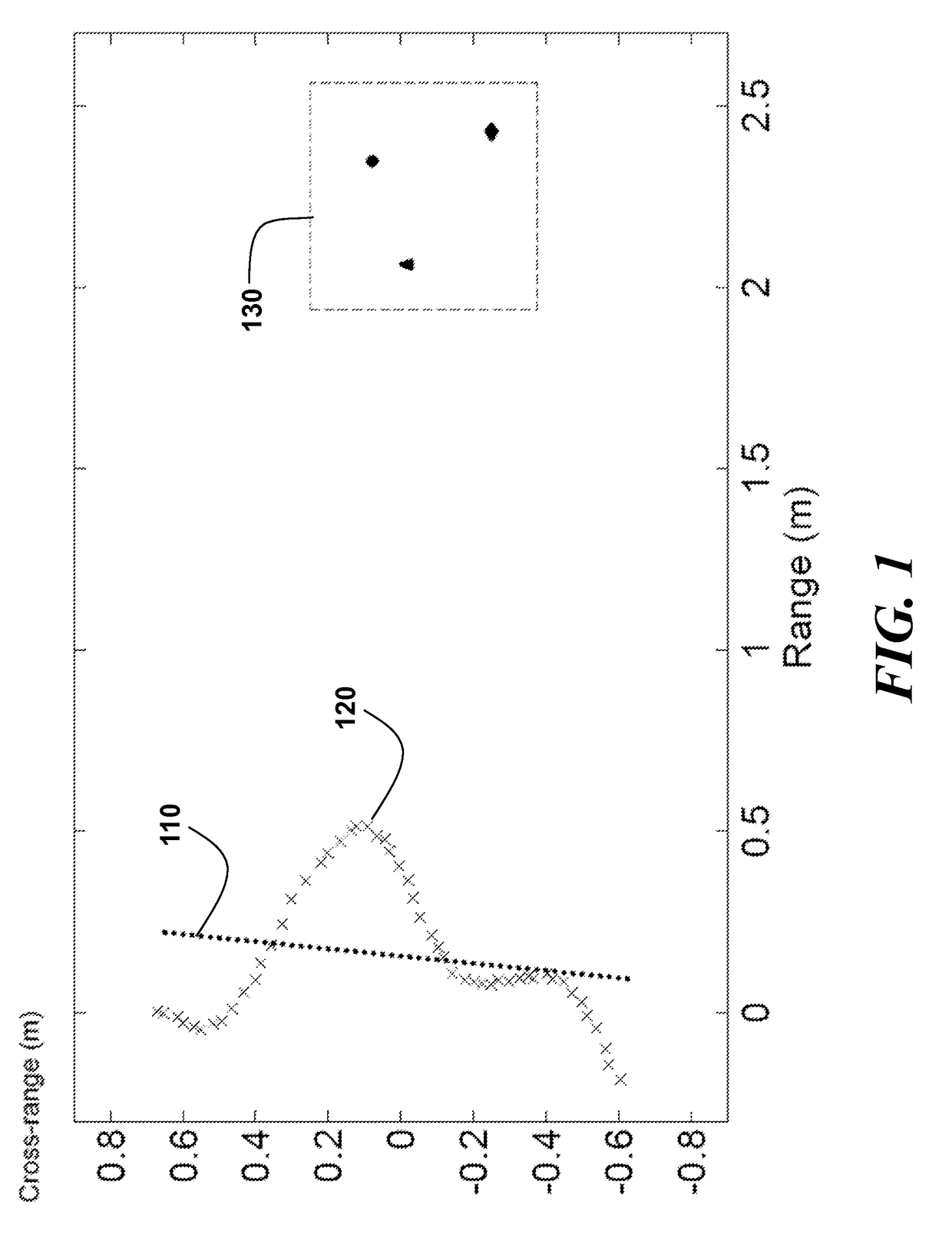
[0016]As schematically shown in FIG. 1, we consider a 2D radar imaging application in which a mono-static radar system is moving along a predesigned trajectory to detect objects located in a region of interest (ROI). The radar system includes a set of antennas. The set can include one or more antennas. Each set of antennas can transmit pulses and receive echoes reflected, e.g., by objects located in the ROI. The pulses form a source signal, and the echoes form a reflected signal. Typically, one antenna transmits the pulses, and one or more antennas receive the echoes.

[0017]For simplicity, we assume that the radar system is moving in a straight line so that the system performs as a linear uniform virtual array, represented by dots 11...


PUM


Abstract

An image of a region of interest (ROI) is generated by a radar system including a set of one or more antennas. The radar system has unknown position perturbations. Pulses are transmitted, as a source signal, to the ROI using the set of antennas at different positions and echoes are received, as a reflected signal, by the set of antennas at the different positions. The reflected signal is deconvolved with the source signal to produce deconvolved data. The deconvolved data are compensated according a coherence between the reflected signal to produce compensated data. Then, a procedure is applied to the compensated data to produce reconstructed data, which are used to reconstruct auto focused images.

Description

FIELD OF THE INVENTION[0001]This invention relates generally to radar imaging, and more particularly to autofocus radar imaging.BACKGROUND OF THE INVENTION[0002]To detect objects in a region of interest (ROI), radar antennas transmit pulses to illuminate the ROI, and receive reflected echoes for an imaging process. The received echoes can be approximated as a weighted sum of delayed versions of the transmitted pulses, with weights related to the reflectivities of the objects and delays related to the ranges of the objects relative to the antennas. Radar imaging is basically an inverse problem to solve for the weights and the delays given the transmitted pulses and the received echoes. When the locations of transmit and receive antennas are known, a simple delay-and-sum method can generate a well-resolved image of the ROI with a sufficient radar aperture size.[0003]However, in radar applications, it is very common that the antenna locations are not known accurately due to environment...

Claims


Application Information

Patent Timeline
IPC IPC(8): G01S13/89
CPCG01S13/89G01S13/9019
Inventor LIU, DEHONG
Owner MITSUBISHI ELECTRIC RES LAB INC
Why Eureka
Try Eureka