Switching Circuit

Active Publication Date: 2017-05-25
DENSO CORP
View PDF2 Cites 0 Cited by
  • Summary
  • Abstract
  • Description
  • Claims
  • Application Information

AI Technical Summary

Benefits of technology

This patent describes a switching circuit that reduces turn-off loss in an insulated-gate bipolar transistor (IGBT) by controlling the current flow during turn-off. The circuit has two control procedures, one for small current flow and the other for large current flow. For small currents, the circuit ensures that the current flows evenly in both transistors, reducing the loads and minimizing turn-off loss. For large currents, the circuit eliminates this relationship and reduces the size of the transistor to be turned off, reducing turn-off loss. The circuit also ensures that the transistors are turned off simultaneously, preventing current flow unevenness and reducing turn-off loss.

Problems solved by technology

In a switching circuit using an IGBT, turn-off loss occurring in the IGBT causes a problem.
However, the inventors have confirmed that, in a case where a current flowing in the IGBT is small, the relationship between the switching rate and the turn-off loss is not established.
That is, it has been confirmed that it is difficult to reduce the turn-off loss of the IGBT at the time of a low current by decreasing the gate resistance.

Method used


Image

  • Switching Circuit
  • Switching Circuit
  • Switching Circuit

Examples


Embodiment Construction

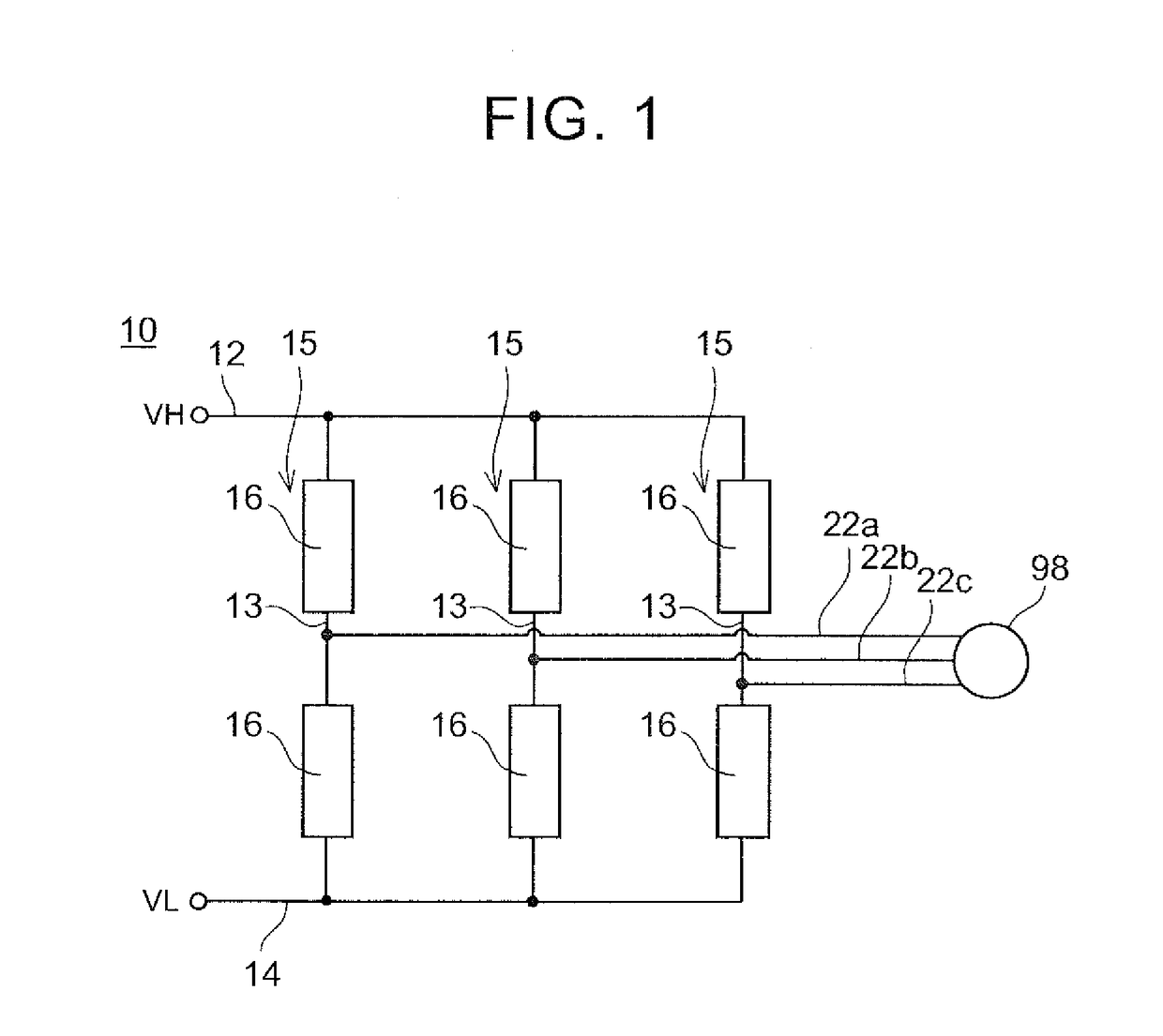
[0038]An inverter circuit 10 shown in FIG. 1 supplies an AC current to a motor 98 for traveling of a vehicle. The inverter circuit 10 has a high-potential wiring 12 and a low-potential wiring 14. The high-potential wiring 12 and the low-potential wiring 14 are connected to a DC power supply (not shown). A high potential VH is applied to the high-potential wiring 12, and a low potential VL is applied to the low-potential wiring 14. Three series circuits 15 are connected in parallel between the high-potential wiring 12 and the low-potential wiring 14. Each series circuit 15 has a connection wiring 13 which is connected between the high-potential wiring 12 and the low-potential wiring 14, and two switching circuits 16 which are provided in the connection wiring 13. The two switching circuits 16 are connected in series between the high-potential wiring 12 and the low-potential wiring 14. Output wirings 22a to 22c are connected to the connection wiring 13 between the two switching circui...


PUM


Abstract

A switching circuit includes a wiring into which a parallel circuit of a first IGBT and a second IGBT is inserted, and a gate control circuit. The gate control circuit has a first switching element configured to control a gate potential of the first IGBT according to a potential of a second principal electrode, and a second switching element configured to control a gate potential of the second IGBT according to a potential of a fourth principal electrode. An output terminal of the control device is connected to the first switching element through a first switch and is connected to the second switching element through a second switch. The control device applies a control signal to the output terminal in a state where the first switch and the second switch are turned on when switching both of the first IGBT and the second IGBT.

Description

INCORPORATION BY REFERENCE[0001]The disclosure of Japanese Patent Application No. 2015-227849 filed on Nov. 20, 2015 including the specification, drawings and abstract is incorporated herein by reference in its entirety.BACKGROUND OF THE INVENTION[0002]1. Field of the Invention[0003]The present invention relates to a switching circuit.[0004]2. Description of Related Art[0005]Japanese Patent Application Publication No. 2004-112916 (JP 2004-112916 A) discloses a switching circuit using a plurality of IGBTs (Insulated Gate Bipolar Transistors). According to the IGBT, a large current can be switched.SUMMARY OF THE INVENTION[0006]In a switching circuit using an IGBT, turn-off loss occurring in the IGBT causes a problem. It is known that the switching rate of the IGBT increases with a decrease in gate resistance. Accordingly, if the switching rate increases, that is, if the gate resistance decreases, turn-off loss decreases. However, the inventors have confirmed that, in a case where a cu...

Claims


Application Information

Patent Timeline
IPC IPC(8): H03K17/06H01L27/06H03K17/567
CPCH03K17/06H03K17/567H01L27/0635H01L29/73H01L29/861H01L28/20H01L23/528H01L29/7393H03K17/168H01L27/0825
Inventor NA, HYOUNGJUNTOSHIYUKI, KENABOU, SHOUJI
Owner DENSO CORP
Why Eureka
Try Eureka