

Projection Optical System and Projector
a technology of projection optical system and projector, which is applied in the direction of optics, projectors, instruments, etc., can solve the problems of difficult to correct off-axis aberration, factor of increasing cost, and high cost of zoom lens attributes, and achieve low cost and high performance.
- Summary
- Abstract
- Description
- Claims
- Application Information
AI Technical Summary
Benefits of technology
Problems solved by technology
Method used
Image

Examples
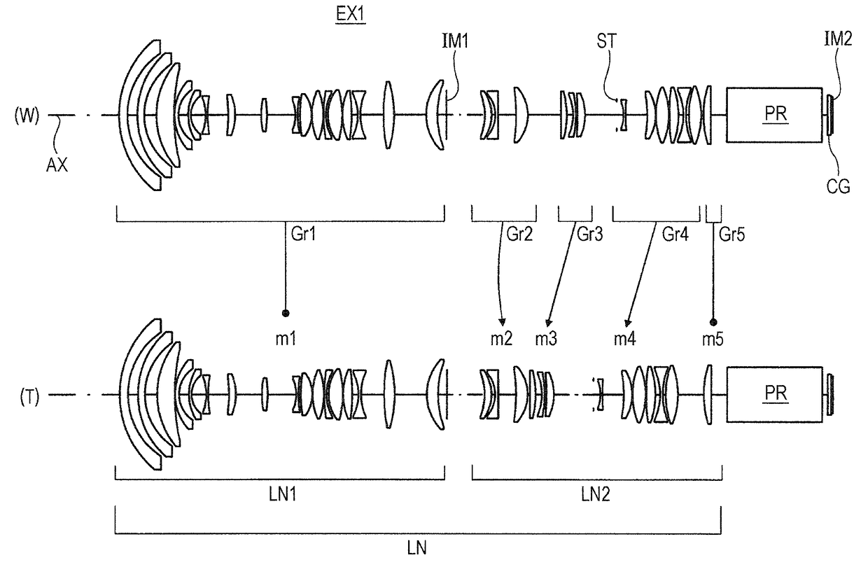
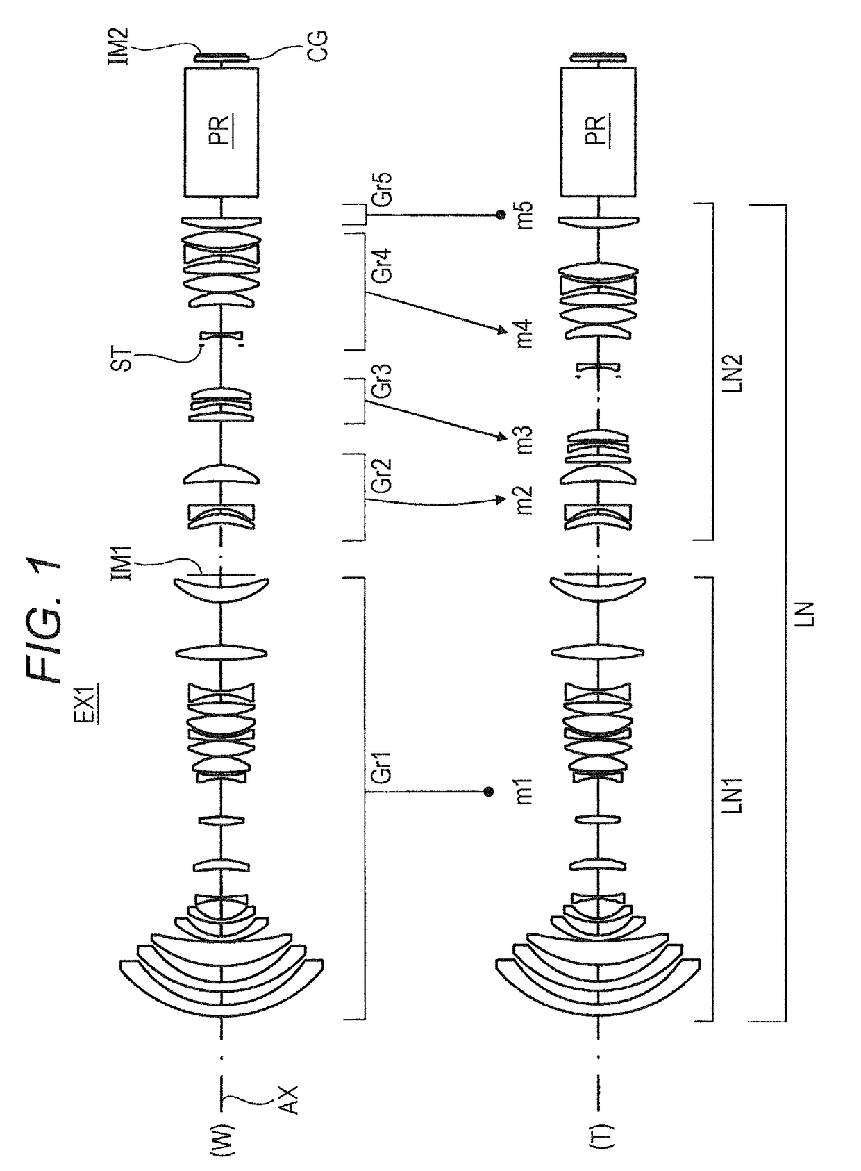
example 1
[0093]
unit: mmSurface datairdndvdobject (SC)infinityinfinity 190.1567.6001.6968055.46 268.9428.958 377.3726.3001.8051825.46 457.95510.706 575.51815.4821.8340037.34 6189.2150.300 746.8263.6001.9537532.32 828.4718.916 945.6622.2001.9108235.251022.31513.08611−47.3321.7001.8061033.271296.44318.54113−185.7346.2841.7291654.6714−50.20523.2951572.9135.0791.8051825.4616−121.42625.61117−36.0742.0001.9036631.311896.7632.02119116.40010.3441.4370095.1020−33.4310.3002156.04910.2561.4370095.1022−65.1650.30023130.3442.1001.9036631.312440.5341.9332538.24312.7301.4370095.1026−91.5240.3002755.8668.1431.4970081.6128−194.7075.80029−42.9012.3001.6200436.303049.12620.62431153.0599.5141.8051825.4632−110.88928.8793345.90010.1351.8051825.463484.0768.02135 (IM1)infinityvariable36−56.9316.2171.8051825.4637−38.4963.35138−29.9892.6001.5928268.6239−4276.23416.37840−156.93310.4821.4874970.4441−38.163variable4219560.3435.2841.9036631.3143−88.5005.67644−46.6392.4001.8051825.4645−104.6891.55246−245.5416.9251.5168064....
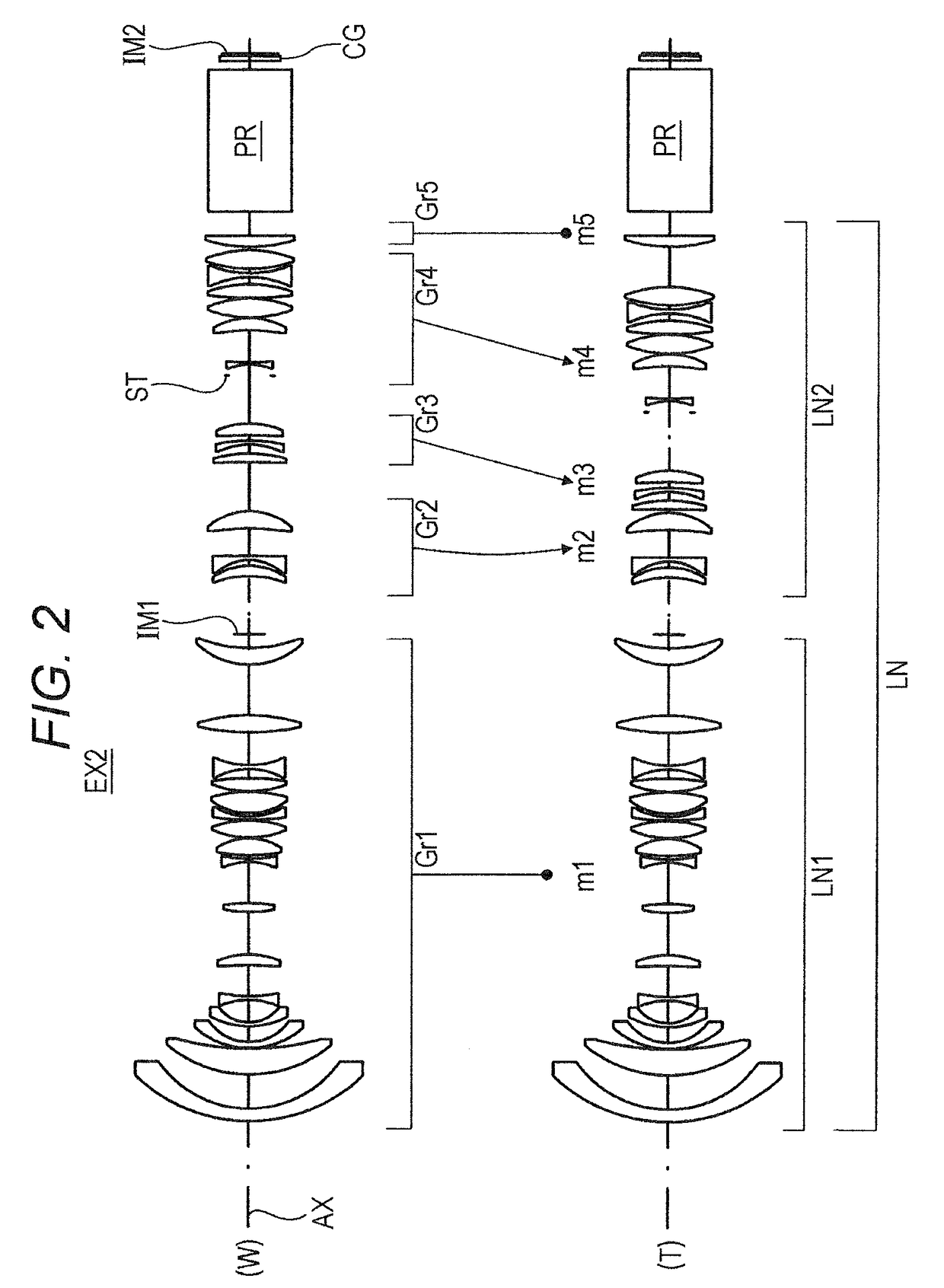
example 2
[0094]
unit: mmSurface datairdndvdobject (SC)infinityinfinity 198.0167.6001.6968055.46 266.27820.460 376.74315.5641.8340037.34 4165.3730.300 549.1893.6001.9537532.32 629.3229.275 747.7192.2681.9108235.25 822.35813.331 9−47.3662.2001.8061033.271080.64018.54511−221.9946.4931.7291654.6712−49.28525.3211371.0595.1481.8051825.4614−130.35424.54515−38.5652.0001.9036631.311681.0781.9951795.44110.4101.4370095.1018−35.1620.3001954.08110.2001.4370095.1020−66.0430.30021141.0712.1001.9036631.312240.4411.8872337.99912.7421.4370095.1024−86.9350.3002560.9577.9661.4970081.6126−146.9565.53127−41.3722.3001.6200436.302847.82720.08829146.20110.3091.8051825.4630−104.50830.6733145.25010.0751.8051825.463279.7098.29933 (IM1)infinityvariable34−57.4326.1671.8051825.4635−38.7353.44436−29.7722.4411.5928268.6237−8921.06016.53438−156.60810.4541.4874970.4439−37.932variable40−859.4425.2661.9036631.3141−81.8495.28942−46.2312.4001.8051825.4643−101.6113.25444−364.9867.0971.5168064.2045−49.543variable46 (ST)infinity6.721...
example 3
[0095]
unit: mmSurface datairdndvdobject (SC)infinityinfinity 1113.9727.6001.6968055.46 276.14512.915 396.11317.3441.7433049.22 4237.9260.300 559.8574.6001.8051825.46 642.5288.660 739.3283.1001.9537532.32 828.1368.267 941.2742.2001.9108235.251021.79513.46911−43.5671.9021.8061033.271286.82217.14313−221.9766.6801.7291654.6714−47.58022.5741573.7785.0691.8051825.4616−123.73426.24517−36.4821.9761.9036631.311894.5862.00019112.16010.0451.4370095.1020−32.5100.3002153.6409.9041.4370095.1022−68.0700.30023120.9812.1001.9036631.312439.7142.1302538.06312.1041.4370095.1026−100.0000.3002756.0707.6451.4970081.6128−221.9735.43629−44.4972.0671.6200436.303047.67418.88231137.8099.2491.8051825.4632−114.76429.9283344.9739.8981.8051825.463477.3888.41835 (IM1)infinityvariable36−62.0656.3791.8051825.4637−39.7323.31038−31.0552.6001.5928268.6239−600.83418.38240−122.5099.7201.4874970.4441−38.985variable423001.2266.3181.9036631.3143−94.6109.76844−47.8632.2401.8051825.4645−110.7453.40046−333.9135.9821.5168064.204...
PUM
 Abstract
Description
Claims
Application Information