
Transient voltage suppressor having built-in-test capability for solid state power controllers

a technology of transistor voltage and solid-state power controller, which is applied in the field of transistor voltage suppression diodes, can solve the problems of mosfet damage or destruction, hundreds of volt surge between a load in the vehicle system and the aircraft chassis, and the material of composite materials not providing the same level of attenuation to lightning

Active Publication Date: 2017-06-01
HAMILTON SUNDSTRAND CORP
View PDF7 Cites 11 Cited by
  • Summary
  • Abstract
  • Description
  • Claims
  • Application Information

AI Technical Summary

Benefits of technology

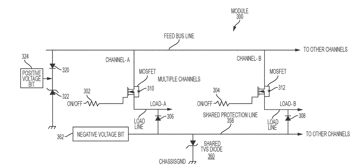
The present patent describes a lightning protection circuit for use in a module with multiple power channels. The circuit includes a shared transient voltage suppressor and a shared protection line that is shared among the power channels. When the shared protection line is shared among the power channels, energy above a certain threshold level on any one channel is dissipated through the shared protection line and the transient voltage suppressor. This design helps to prevent damage caused by lightning strikes in the module. Another embodiment of the patent describes a method for forming the lightning protection circuit. Overall, the patent provides a solution for protecting multiple power channels from lightning strikes in a module.

Problems solved by technology

However, composite materials do not provide the same level of attenuation to lightning as aluminum.
When lightning occurs, hundreds of volts may surge between a load in the vehicle system and the aircraft chassis.
When these MOSFETs are subjected to lightning-induced power surges and other transients that are higher than the MOSFET voltage ratings and they are OFF, the MOSFETs break down and conduct, which typically results in the MOSFET being damaged or destroyed.
Additionally, although TVS diodes have sufficient functionality to provide the necessary transient protection, known TVS designs exhibit dormant failures.
Existing SSPCs that utilize TVS diode-based protection transient protection schemes do not have a way of testing the full functionality of its protection circuitry without removing the module containing the protection circuitry from the aircraft itself.

Method used


Image

  • Transient voltage suppressor having built-in-test capability for solid state power controllers
  • Transient voltage suppressor having built-in-test capability for solid state power controllers
  • Transient voltage suppressor having built-in-test capability for solid state power controllers

Examples


Embodiment Construction

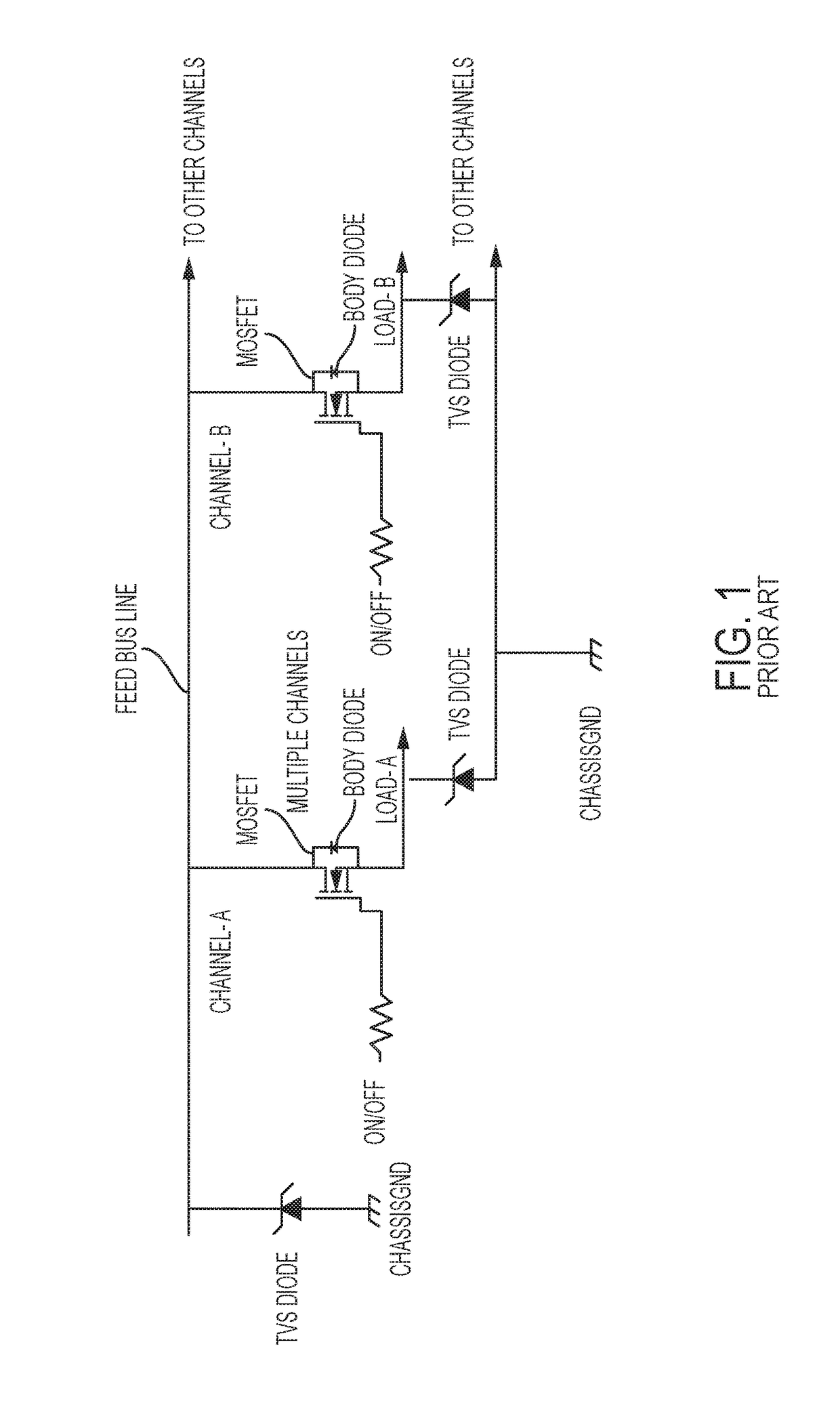
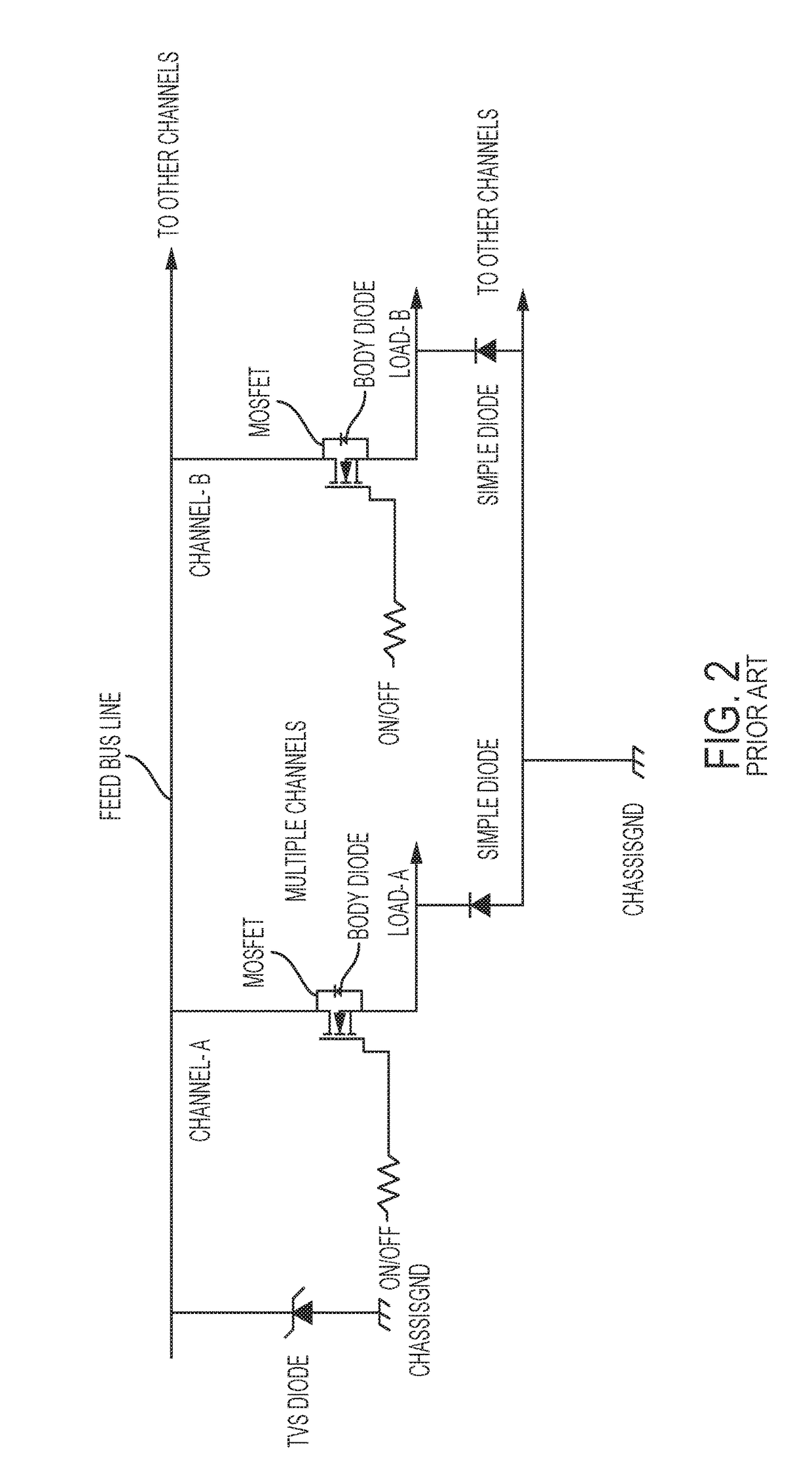
[0017]Turning now to an overview of the present disclosure, PMD systems generally include modules that each includes multiple SSPC power channels. Each power channel has an input feed line, an output load and a power MOSFET that selectively couples the feed voltage to the output load when turned on. When the power MOSFET switch of a given channel is subjected to a voltage transient (e.g., a lightning induced transient) that is higher than the MOSFET voltage rating limit and it is OFF, the MOSFET will break down and conduct and usually be damaged or destroyed. Existing transient protection / suppression systems, examples of which are shown in FIGS. 1 and 2, provide transient protection. However, as the number of channels provided on an SSPC card continues to increase (e.g., up to about 40 SSPC channels per SSPC card), the complexity, cost and card area required to implement existing transient protection schemes continue to increase as well.

[0018]In one or more embodiments of the presen...


PUM


Abstract

Embodiments are directed to a transient protection circuit configured for use in a SSPC having a plurality of power channels. The transient protection circuit includes a shared transient voltage suppressor, and a shared protection line communicatively coupled to the shared transient voltage suppressor. The shared protection line is configured to be communicatively coupled to and shared by the plurality of power channels. When the shared protection line is communicatively coupled to and shared by the plurality of power channels, energy above a threshold on any one of the plurality of power channels is dissipated through the shared protection line and the shared transient voltage suppressor.

Description

BACKGROUND OF THE DISCLOSURE[0001]The present disclosure relates generally to the use of transient voltage suppression (TVS) diodes to protect aircraft power control circuitry and their components from transient power surges. More specifically, the present disclosure relates to TVS diode-based protection schemes that facilitate the efficient and cost effective protection of solid state power controller (SSPC) components from exposure to overvoltage conditions caused by lightning-induced pulses and other transient events, while also facilitating the efficient and cost effective incorporation of built-in-test (BIT) circuitry for TVS diode failure detection.[0002]Vehicles, such as aircraft, typically include miles of wires and dozens of computers and other instruments and systems that control everything from the engines to passenger headsets. One or more power management and distribution (PMD) systems are typically provided to distribute power from a primary source to various vehicle s...

Claims


Application Information

Patent Timeline
Patent Type & Authority Applications(United States)
IPC IPC(8): H02H9/04H02H9/00
CPCH02H9/005H02H9/042B64D2221/00G01R31/2632G01R31/2827G01R31/3277H02H3/044H02H3/048H02H7/268H02H9/041H02H9/049H03K17/08142H03K17/74
Inventor DICKEY, JOHN A.KILROY, DONALD G.SWENSON, JOSH C.
Owner HAMILTON SUNDSTRAND CORP
Learn More