Apparatus and method for controlling permanent magnet motor

Active Publication Date: 2017-06-01
KOREA INST OF IND TECH
View PDF5 Cites 6 Cited by
  • Summary
  • Abstract
  • Description
  • Claims
  • Application Information

AI Technical Summary

Benefits of technology

The patent describes an apparatus and method for controlling a permanent magnet motor that can effectively control magnetic flux based on the motor's actual current. This results in increased efficiency of the motor. Additionally, the apparatus can calculate an optimal magnetic flux even when the motor is exposed to different environmental factors, such as aging, which can change the motor's performance. This ensures that the motor operates at its optimal level regardless of the environment.

Problems solved by technology

Meanwhile, a conventional permanent magnet motor mostly uses magnetization current control or demagnetization current control because controlling the magnetic flux itself to vary the magnetic flux for selectively controlling the speed or torque is very difficult.
However, since magnetic flux of a motor cannot be accurately controlled only by the control of magnetization current or demagnetization current, and particularly, the magnetization current and demagnetization current used for the control are initially set or have a fixed value, there is a problem in that control of a motor cannot adapt to environmental changes such as aging of the motor or the like.

Method used


Image

  • Apparatus and method for controlling permanent magnet motor
  • Apparatus and method for controlling permanent magnet motor
  • Apparatus and method for controlling permanent magnet motor

Examples


Embodiment Construction

[0031]Hereinafter, embodiments of the present invention will be described in detail with reference to the accompanying drawings so that those skilled in the art of the technical field to which the present invention belongs may easily implement the technical sprit of the present invention. The present invention may, however, be embodied in various different forms and is not to be construed as limited to the embodiments set forth herein. Further, in the drawings, for the sake of clarity of the present invention, portions unrelated to the explanation may be omitted from the illustration, and like numbers refer to like elements throughout the specification.

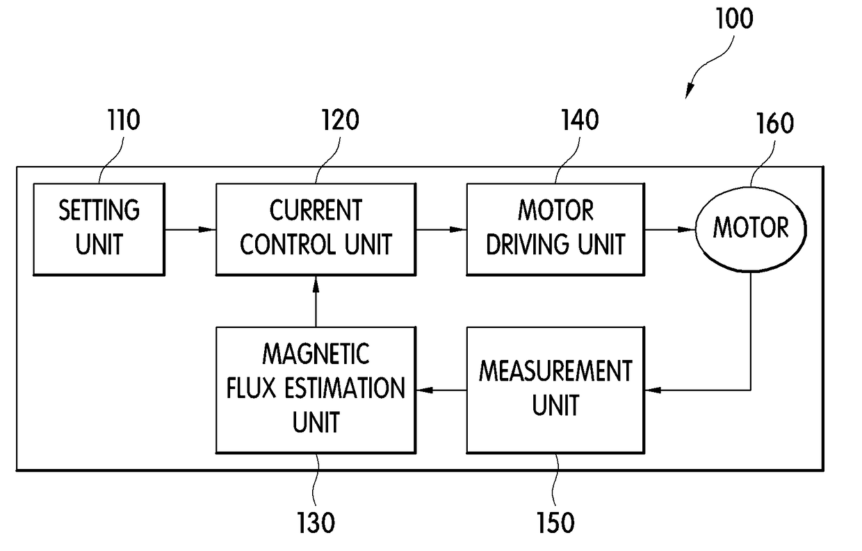
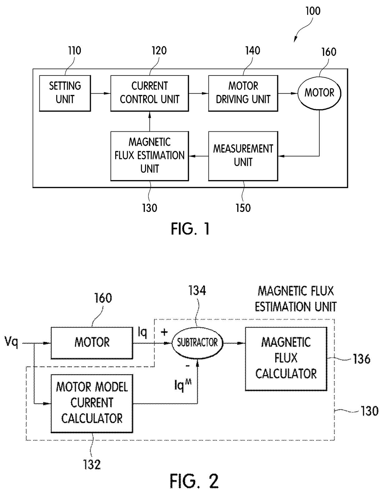
[0032]FIG. 1 is a block diagram of an apparatus for controlling a permanent magnet motor according to one embodiment of the present invention. Hereinafter, an apparatus for controlling a permanent magnet motor according to one embodiment of the present invention will be described in detail with reference to the accompanying drawings.

[...


PUM


Abstract

An apparatus and a method for controlling a permanent magnet motor are provided. An apparatus for controlling a permanent magnet motor, according to an embodiment of the present invention, comprises: a current control unit for generating a control current so as to drive a motor according to an initial set current or a current corresponding to an estimated magnetic flux; a motor driving unit for driving the motor according to the control current of the current control unit; a measurement unit for measuring a driving voltage and current of the motor; and a magnetic flux estimation unit preliminarily driving the motor with the initial set current or the current corresponding to the estimated magnetic flux, so as to estimate the magnetic flux of the motor on the basis of the current measured when the motor is preliminarily driven and a voltage model of the motor according to the measured voltage, and adaptively controlling the magnetization current or demagnetization current of the motor such that the estimated magnetic flux is within an error range.

Description

TECHNICAL FIELD[0001]The present invention relates to an apparatus and method for controlling a permanent magnet motor, and more particularly, to an apparatus and method for controlling a variable magnetic flux motor.BACKGROUND ART[0002]Generally, a permanent magnet motor is operated in a speed control mode or torque control mode and a method of controlling both speed and torque may be used depending on applications, and in the latter case, a variable magnetic flux permanent magnet motor in which magnetic flux of the permanent magnet is variable depending on operation modes is used.[0003]In such a variable magnetic flux permanent magnet motor, magnetic flux of the motor is varied by magnetization or demagnetization. For example, in the case of a washing machine, which is a typical application of the variable magnetic flux permanent magnet motor, magnetic flux of the motor is varied by changing a magnetizing amount or demagnetizing amount of the permanent magnet because high-speed ro...

Claims


Application Information

Patent Timeline
IPC IPC(8): H02P21/14H02P6/28
CPCH02P6/28H02P21/141H02P6/20H02P21/24H02P21/34
Inventor KIM, MYUNG BOKLEE, SUNG HOKWAK, BONG WOO
Owner KOREA INST OF IND TECH
Why Eureka
Try Eureka