Highly flexible stent

a stent and flexible technology, applied in the field of high-flexible stents, can solve the problems of inability to adapt to the needs of patients, lack of flexibility of the structure, and inability to inhibit the flow of liquid, so as to achieve high flexibility and suppress the amount of deformation

Inactive Publication Date: 2017-06-08
BIOMEDICAL SOLUTIONS
View PDF2 Cites 72 Cited by
  • Summary
  • Abstract
  • Description
  • Claims
  • Application Information

AI Technical Summary

Benefits of technology

The present invention provides a stent that is flexible and can prevent the stent from expanding too much when it is bent or distorted.

Problems solved by technology

However, for such an open cell structure, since a part of a strut of the stent may protrude radially outward in a flared shape when bent, there is a risk of damaging the tissue of a tubular organ in a body such as blood vessels when the stent is placed therein.
For such a closed cell structure, although there is no risk of the strut of the stent protruding radially outward such as a stent having an open cell structure, the flexibility of the structure tends to be lacking.
Therefore, there has been a risk of inhibiting the flow of liquid such as blood in tubular organs from flowing due to a stent buckling when applying the stent having a closed cell structure to a bent tubular organ.
Furthermore, structurally speaking, since the stent having a closed cell structure is inferior to the stent having an open cell structure in terms of a reduction in diameter, the stent having a closed cell structure cannot handle placement of a stent into a tubular organ of small diameter of around 2 mm, a result of which there has been a risk of damaging a body tissue.

Method used


Image

  • Highly flexible stent
  • Highly flexible stent
  • Highly flexible stent

Examples


first embodiment

[0115]FIG. 11A shows a central axis of a cross section of the stent and a side view of a blood vessel. FIG. 11B is a schematic view of a cross section of the stent where the central axis is not displaced. FIG. 11C is a schematic view of a cross section of the stent where the central axis is displaced. FIG. 12 is a schematic view showing a malapposition. FIG. 13 is a schematic view of a developed view of a highly flexible stent in an unloaded state according to the present invention. FIG. 14 is a schematic view showing the behavior of a coiled element and the center of the figure when the stent shown in FIG. 13 is bent. FIG. 15 is a schematic view showing a behavior of the center of the figure of a cross section of the stent bent. FIG. 16 is a schematic view showing a behavior in a case in which a distortion in a right-hand direction is applied to the stent shown in FIG. 13. FIG. 17 is a schematic view showing a behavior in a case in which a distortion in a left-hand direction is app...

second embodiment

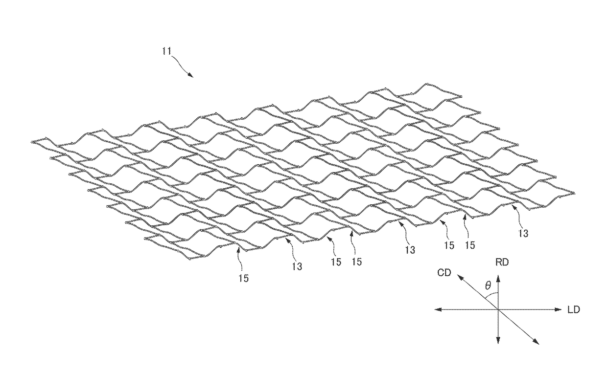
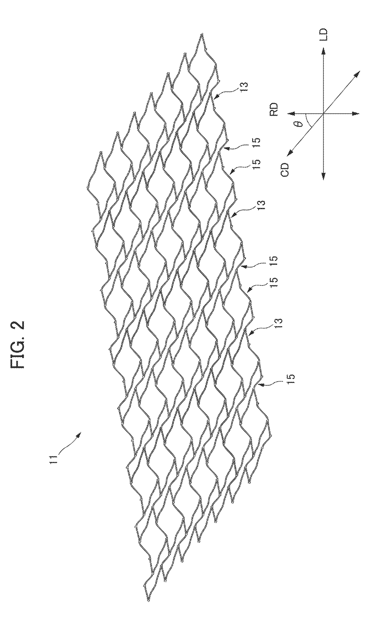
[0143]The stent 11A has a single spiral structure. As shown in FIG. 21, the single spiral structure is a structure in which there is a single spiral L28 between the joining points Δ (triangle) in the reference line L20 extending in the radial direction RD. The wavy-line pattern of a circular body 13 is a zigzagged shape. A virtual line L29 passing through a plurality of apices 17b on the same side of the zigzagged shape is linear.

[0144]It should be noted that the stent 11A according to the second embodiment shown in FIG. 21 and the stent 11 according to the first embodiment shown in FIG. 2 are in a mirror image relationship in the axial direction LD. X(1), X(2), X(3), and X(4) in FIG. 21 are used for explaining modified examples described later.

[0145]In the stent 11 according to the first embodiment shown in FIG. 2 and the stent 11A according to the second embodiment shown in FIG. 21, the wavy-line pattern body 13 forms a circular body. On the other hand, in the present invention, ...

fourth embodiment

[0156]FIG. 30 is a developed view showing a stent 11C according to the present invention to be virtually expanded into a plane.


PUM


Abstract

A stent includes wavy-line pattern bodies having a wavy-line pattern and arranged side-by-side in an axial direction LD, and coiled elements arranged between the wavy-line pattern bodies adjacent and extending in a spiral manner around an axis. All apices on opposite sides of the wavy-line pattern of the wavy-line pattern bodies that are adjacent are connected by way of the coiled element. When viewing in a radial direction RD, a circular direction CD of the wavy-line pattern bodies is inclined with respect to the radial direction RD, and a winding direction of one of the coiled elements located at one side in the axial direction LD with respect to the wavy-line pattern bodies and a winding direction of one other of the coiled elements located at the other side in the axial direction LD are opposite.

Description

CROSS-REFERENCE TO RELATED APPLICATIONS[0001]This application is a Continuation of co-pending application Ser. No. 14 / 408,203, filed on Dec. 15, 2014, which is a U.S. National Stage of International Application No. PCT / JP2014 / 071469 filed on Aug. 15, 2014, for which priority is claimed under 35 U.S.C. §120; and this application claims priority of Application No. 2014-029933 filed in Japan on Feb. 19, 2014 and Application No. 2014 / 165104 filed in Japan on August 154, 2014 under 35 U.S.C. §119; the entire contents of all of which are hereby incorporated by reference.TECHNICAL FIELD[0002]The present invention relates to a highly flexible stent placed in a luminal structure of a living body in order to expand lumen.BACKGROUND ART[0003]In a biological organ having a luminal structure such as blood vessels, the trachea and the intestines, when stenosis occurs therein, a cylinder-shaped stent with mesh pattern is used in order to secure patency at a site of pathology by expanding an inner ...

Claims


Application Information

Patent Timeline
Patent Type & Authority Applications(United States)
IPC IPC(8): A61F2/92A61F2/966A61F2/915
CPCA61F2/92A61F2/915A61F2/966A61F2002/9155A61F2230/0006A61F2230/0091A61F2002/91575A61F2230/0054A61F2230/0023A61F2230/0069A61F2/95A61F2/89A61B17/22A61F2/01A61F2/88
Inventor SHOBAYASHI, YASUHIRO
Owner BIOMEDICAL SOLUTIONS
Why Eureka
Try Eureka