
Method for producing intermetallic compound

a technology of intermetallic compounds and compound, which is applied in the direction of manufacturing tools, welding/cutting media/materials, and manufacturing tools, etc., can solve the problems of voids near the intermetallic compound, reducing the bonding strength, and generating a large amount of gas, so as to reduce the generation of voids and reduce the heat resistance unreacted

Pending Publication Date: 2017-06-08
MURATA MFG CO LTD
View PDF3 Cites 4 Cited by
  • Summary
  • Abstract
  • Description
  • Claims
  • Application Information

AI Technical Summary

Benefits of technology

The present invention provides a method for producing an intermetallic compound with a dense and high heat-resistant structure. The method involves heating a mixture of two metal powders at different temperatures and for different periods of time to produce the intermetallic compound. The first heating step melts the first metal and spreads it around the second metal powder, while the second heating step accelerates the reaction between the two metals to produce the intermetallic compound. This method can reduce gas generation and voids in the intermetallic compound, resulting in a more dense structure. Additionally, the method can reduce sites without contact between the two metals, resulting in a more efficient reaction and a higher heat-resistant structure.

Problems solved by technology

However, when the solder paste in Patent Document 1 is heated for a long period of time as shown in FIG. 6, the flux component in the solder paste is thermally decomposed, thereby generating a large amount of gas.
As a result, a large volume of voids (air bubbles) is likely to be generated in the bonding member containing the intermetallic compound as its main phase, and there is thus a tendency to decrease the bonding strength.
In addition, in the formation of the intermetallic compound, imbalances in interdiffusion between the Sn and the CuNi alloy may cause voids near the intermetallic compound.
On the other hand, when the time for heating the solder paste is short, the reaction for the production of the intermetallic compound tends to proceed insufficiently, thereby leaving a large amount of low heat-resistance unreacted Sn.

Method used


Image

  • Method for producing intermetallic compound
  • Method for producing intermetallic compound
  • Method for producing intermetallic compound

Examples


Embodiment Construction

[0030]A method for producing an intermetallic compound according to an embodiment of the present invention will be described below.

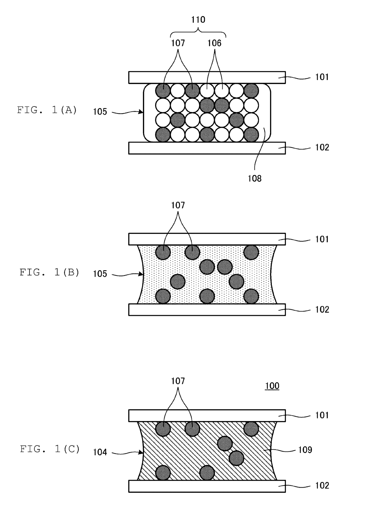
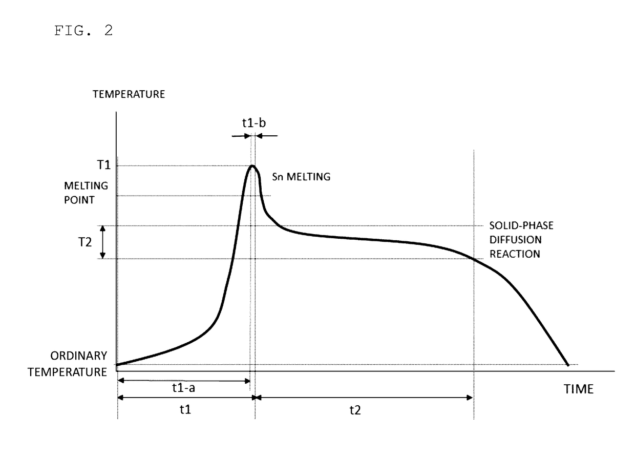
[0031]FIGS. 1(A) TO 1(C) are cross-sectional views schematically illustrating a process for producing an intermetallic compound that is produced by a method for producing an intermetallic compound according to the embodiment of the present invention. FIG. 2 is a diagram showing a temperature profile for a heating step carried out in a method for producing an intermetallic compound according to the embodiment of the present invention.

[0032]First, a metal paste 105 is prepared. The metal paste 105 is, as shown in FIG. 1(A), used for, for example, bonding a first object 101 to be bonded and a second object 102 to be bonded. In this regard, the metal paste 105 corresponds to the mixture according to the present invention.

[0033]The first object 101 to be bonded is a pipe, a nut, and an electronic component such as a multilayer ceramic capacitor, for example. ...


PUM

PropertyMeasurementUnit
temperature T2aaaaaaaaaa
temperatureaaaaaaaaaa

Abstract

A metal paste that includes a metal component and a flux. The metal component includes a first metal powder and a second metal powder. The first metal powder is Sn. The second metal powder is a CuNi alloy. The metal paste is heated for a time t1 to a temperature T1 where the first metal powder is melted. Next, the metal paste is heated for a time t2 longer than the time t1 at a temperature T2 lower than the temperature T1 to produce an intermetallic compound from the first metal Sn and the second metal CuNi alloy.

Description

CROSS REFERENCE TO RELATED APPLICATIONS[0001]The present application is a continuation of International application No. PCT / JP2015 / 072597, filed Aug. 10, 2015, which claims priority to Japanese Patent Application No. 2014-184052, filed Sep. 10, 2014, the entire contents of each of which are incorporated herein by reference.FIELD OF THE INVENTION[0002]The present invention relates to a method for producing an intermetallic compound that is produced by heating a mixture including a first metal and a second metal.BACKGROUND OF THE INVENTION[0003]Conventionally, methods for producing intermetallic compounds are known, which include heating a mixture including a first metal and a second metal that can react with the first metal to produce an intermetallic compound. For example, Patent Document 1 discloses a bonded structure and a bonding method with an intermetallic compound produced by heating a solder paste (mixture). The solder paste includes a metal component including a Sn powder an...

Claims


Application Information

Patent Timeline
Patent Type & Authority Applications(United States)
IPC IPC(8): C22C1/02B23K35/30C22C13/00B23K35/26
CPCC22C1/02B23K35/262C22C13/00B23K35/3033B23K35/302B23K35/26B23K35/30B23K35/22C22C1/00B23K35/0244H05K3/3494H05K3/3485
Inventor WASHIZUKA, SEITARO
Owner MURATA MFG CO LTD
Learn More