Mlu based accelerometer using a magnetic tunnel junction

a magnetic tunnel junction and accelerometer technology, applied in the direction of speed/acceleration/shock measurement, magnetic measurement, instruments, etc., can solve the problems of thermal noise, capacitive accelerometers struggling at micro-g variations, and higher manufacturing process costs, so as to achieve greater sensibility and lower static power consumption

a magnetic tunnel junction and accelerometer technology, applied in the direction of speed/acceleration/shock measurement, magnetic measurement, instruments, etc., can solve the problems of thermal noise, capacitive accelerometers struggling at micro-g variations, and higher manufacturing process costs, so as to achieve greater sensibility and lower static power consumption

US20170160308A1Active Publication Date: 2017-06-08CROCUS TECHNOLOGY

Image

  • Mlu based accelerometer using a magnetic tunnel junction
  • Mlu based accelerometer using a magnetic tunnel junction
  • Mlu based accelerometer using a magnetic tunnel junction

Examples


Embodiment Construction

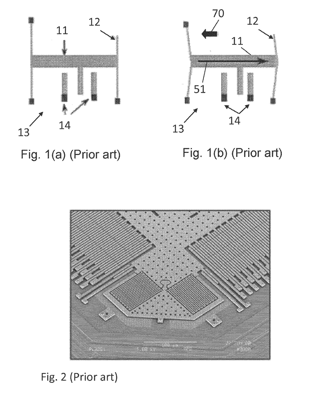
[0030]The principle of the invention is to replace the capacitances in the MEMS accelerometers by MLU stacks that can be considered as variable resistors. The accelerometer will still be based on a proof-mass system. However, the comb-architecture that capacitive accelerometers require will not be necessary.

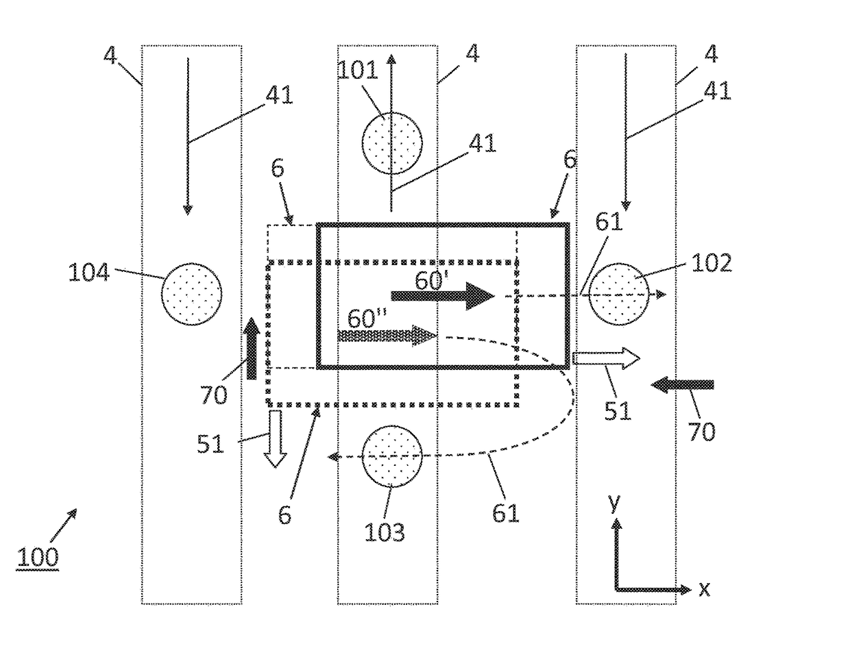
[0031]A top view of a two-dimensional MLU-based accelerometer 100 is pictured in FIG. 4, according to an embodiment. The MLU-based accelerometer 100 comprises a proof-mass 6 comprising a ferromagnetic material having a proof-mass magnetization 60 oriented in a predetermined direction inducing a proof-mass filed 61. The proof-mass 6 is suspended by a spring element 62 such that, when the accelerometer 100 is subjected to an acceleration vector, the proof-mass 6 is deflected in a direction opposed to the direction of the acceleration vector. In the example of FIG. 4, the two-dimensional MLU-based accelerometer 100 comprises four flexible beams 62 acting as spring element and locate...


PUM


Abstract

An MLU-based accelerometer including: at least one MLU including a tunnel barrier layer between a first magnetic layer having a fixed first magnetization direction and a second magnetic layer having a second magnetization direction that can be varied. A proof-mass includes a ferromagnetic material having a proof-mass magnetization inducing a proof-mass field, the proof-mass being elastically suspended such as to be deflected in at least one direction when subjected to an acceleration vector. The proof-mass is magnetically coupled to the MLU cell via the proof-mass field. A read module is configured for determining a magnetoresistance of each MLU cell such as to determine an acceleration vector from the deflection of the proof-mass relative to any one of the at least one MLU cell.

Description

FIELD OF THE INVENTION[0001]The present invention concerns an accelerometer device that has an increased sensitivity.DESCRIPTION OF RELATED ART[0002]An accelerometer is a MEMS device that is used to measure acceleration forces. The traditional applications include vibration measurement, earthquake detection and seismic applications. One of the most common uses for MEMS accelerometers is in airbag deployment systems for automobiles and in potentially all smartphone and tablets. The widespread use of accelerometers in the automotive and mobile industry has dramatically reduced their cost. In the present market, single-axis, dual-axis, and three-axis models are commonly available. The performance of capacitive accelerometers has been dramatically improved since the first microaccelerometer was introduced.[0003]Displacement accelerometers measure the displacement of a suspended proof-mass in response to an input acceleration. FIG. 1 (left) shows a schematic of a capacitive-based acceler...

Claims


Application Information

Patent Timeline
08 Jun 2017
Publication
US20170160308A1
IPC
G01P15/105; G01R33/09; G01P15/18
CPC
G01P15/105; G01R33/098; G01P15/18; G01D5/145; G01P15/0802; G01P15/0885
Inventors
ALAOUI, ALI