Method for reducing fronthaul load in centralized radio access networks (c-ran)

a radio access network and fronthaul load technology, applied in the field of mobile communication networks, can solve the problems of affecting the flexibility of conventional cran systems where signal processing operations are delegated to central units, further burdening the central unit, and not fully satisfying modern technological requirements, so as to reduce the data rate of signals transmitted on fiber links

Active Publication Date: 2017-06-08
TELECOM ITALIA SPA
View PDF1 Cites 18 Cited by
  • Summary
  • Abstract
  • Description
  • Claims
  • Application Information

AI Technical Summary

Benefits of technology

[0015]These issues are exacerbated in CRAN systems relying on signal processing algorithms operating on each user signal separately (such as “adaptive beamforming” and “network coordination” algorithms), as application of such algorithms requires that signal processing operations are performed at a central unit side (wherein the user signals are still separately available), thus further burdening the central unit. The applicant thus believes that for effective application of such algorithms, data rate of the signals transmitted on the fiber links should be reduced.

Problems solved by technology

The Applicant has found that the above-cited solutions are not fully satisfactory for modern technological requirements.
Specifically, the Applicant has found that conventional CRAN systems wherein signal processing operations are delegated to the central units are affected by flexibility issues, as any algorithm changes may involve software and / or hardware modifications in the central unit, as well as scalability issues, as involving a limitation on a maximum number of remote units that can be connected to a given central unit.
These issues are exacerbated in CRAN systems relying on signal processing algorithms operating on each user signal separately (such as “adaptive beamforming” and “network coordination” algorithms), as application of such algorithms requires that signal processing operations are performed at a central unit side (wherein the user signals are still separately available), thus further burdening the central unit.

Method used


Image

  • Method for reducing fronthaul load in centralized radio access networks (c-ran)
  • Method for reducing fronthaul load in centralized radio access networks (c-ran)
  • Method for reducing fronthaul load in centralized radio access networks (c-ran)

Examples


first embodiment

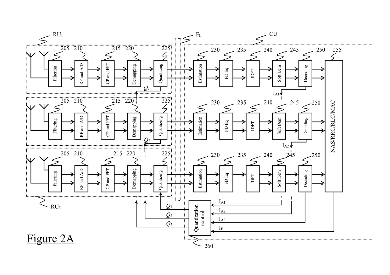
[0061]Specifically, with reference now to FIG. 2A, schematically showing some relevant modules of central CU and remote RUj (e.g., RU1-RU3) units according to the present invention, channel estimation (module 230), frequency-domain equalization (module 235), “Inverse Discrete Fourier Transformation” (IDFT) precoding (module 240), soft-demodulation (i.e., symbol-to-bit demapping) (module 245), channel decoding (module 250) and higher layer protocols functionalities such as “Non Access Stratum” (NAS), “Radio Resource Control” (RRC), “Radio Link Control” (RLC) and “Medium Access Control” (MAC) layers (module 255) are performed in the central unit CU, whereas filtering (module 205), radio-frequency processing and analog-to-digital conversion (module 210), “Cyclic Prefix” (CP) removal and “Fast Fourier Transformation” (FFT) (module 215), resource element demapping (module 220), and quantization (module 225) are performed in each remote unit RUj—however, embodiments wherein the demapping ...

second embodiment

[0082]In this respect, FIG. 2B schematically shows some relevant modules of central CU′ and remote RU′j (e.g., RU′1-RU′3) units according to the present invention. In this embodiment, filtering (module 205), radio-frequency processing and analog-to-digital conversion (module 210), “Cyclic Prefix” (CP) removal and “Fast Fourier Transformation” (FFT) (module 215), resource element demapping (module 220), channel estimation (module 230), frequency-domain equalization (module 235), “Inverse Discrete Fourier Transformation” (IDFT) precoding (module 240), soft-demodulation (i.e., symbol-to-bit demapping) (module 245) and quantization (module 225) are performed (preferably in this order) in each remote unit RU′j, whereas channel decoding (module 250) and higher layer protocols functionalities such as “Non Access Stratum” (NAS), “Radio Resource Control” (RRC), “Radio Link Control” (RLC) and “Medium Access Control” (MAC) layers (module 255) are still performed in the central unit CU′.

[0083]T...


PUM


Abstract

A method is proposed of arranging, in a mobile communication network, transmission of data between user equipment and at least one base station including a central unit and at least one remote unit associated therewith. The method includes at a transmitting side including the remote unit or the central unit, quantizing the data according to a quantization bit number, and transmitting, over a fronthaul link between the transmitting side and a receiving side including the central unit or the remote unit, respectively, the quantized data to the receiving side. The method further includes, at the central unit: determining the quantization bit number, wherein the determining including varying in time the quantization bit number according to network information available at the central unit, and communicating to the at least one remote unit the determined quantization bit number.

Description

BACKGROUND OF THE INVENTION[0001]Field of the Invention[0002]The present invention generally relates to mobile communication networks—hereinafter, mobile networks. More specifically, the present invention relates to mobile networks based on a “Centralized Radio Access Network” (CRAN) architecture—shortly, CRAN systems.[0003]The work leading to the present invention has received funding from the European Union's Seventh Framework Program FP7 / 2007-2013 under grant agreement n. 317941—project iJOIN.[0004]Overview of the Related Art[0005]A CRAN system typically comprises one or more central units each one connected to a plurality of remote units (preferably by means of respective optical fiber links).[0006]According to a conventional CRAN system architecture, in the downlink, the central unit receives data to be transmitted to user equipment of the mobile network, and provides a digital base-band signal. The digital base-band signal is then converted from electrical to optical, and tran...

Claims


Application Information

Patent Timeline
Patent Type & Authority Applications(United States)
IPC IPC(8): H04W28/08H04B10/2575H04L27/26
CPCH04W28/08H04W88/085H04B10/25758H04L27/2602H03M7/3059H04L27/2601H04B10/25753H04W28/16
Inventor BOLDI, MAUROGIANOLA, PAOLOMELIS, BRUNO
Owner TELECOM ITALIA SPA
Why Eureka
Try Eureka