Operating method of full-bridge modular multilevel converter boosting ac voltages

a multi-level, converter technology, applied in the direction of power conversion systems, electric power transfer ac networks, electrical apparatus, etc., can solve the problems of reducing the transmission capacity of the converter

Active Publication Date: 2017-06-15
HUAZHONG UNIV OF SCI & TECH
View PDF3 Cites 18 Cited by
  • Summary
  • Abstract
  • Description
  • Claims
  • Application Information

AI Technical Summary

Benefits of technology

[0013]Increasing peak values of AC-side voltages under a constant DC-link voltage by using FBSMs' negative output voltage in steady state, wherein keeping the semiconductor's current rating constant after AC-side voltage boosting is in favor of reducing converter cost by decreasing energy interaction between the upper and lower arms in a leg, and further capacitance value of FBSM's capacitor under a constant capacitor voltage ripple, keeping RMS value of AC phase currents constant after AC-side voltage boosting can effectively improve transmission capacity of the converter while reducing converter cost, and keeping converter transmission capacity constant after AC-side voltage boosting can reduce the RMS value of arm currents while reducing converter cost, thereby reducing power loss of FBSMs and improving converter efficiency.
[0014]FIG. 1 is a flow chart of an operating method of a FBSM based modular multilevel convert...

Problems solved by technology

However, breakers on AC side can only clear the DC fault at the zero crossing point of AC-side current meaning considerable delay time existing before the breaker acts, and the DC short circuit fault can be turned into an AC short circuit fault.
In addition, the reclosing timing sequence for an AC breaker is comparativ...

Method used


Image

  • Operating method of full-bridge modular multilevel converter boosting ac voltages
  • Operating method of full-bridge modular multilevel converter boosting ac voltages
  • Operating method of full-bridge modular multilevel converter boosting ac voltages

Examples


embodiment 1

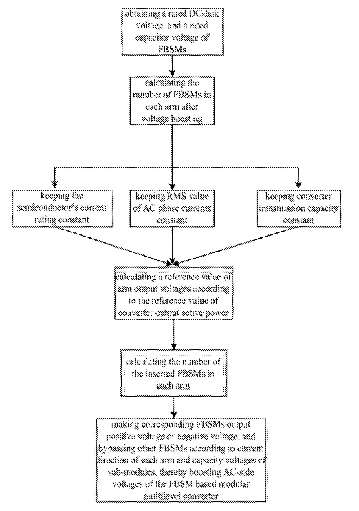
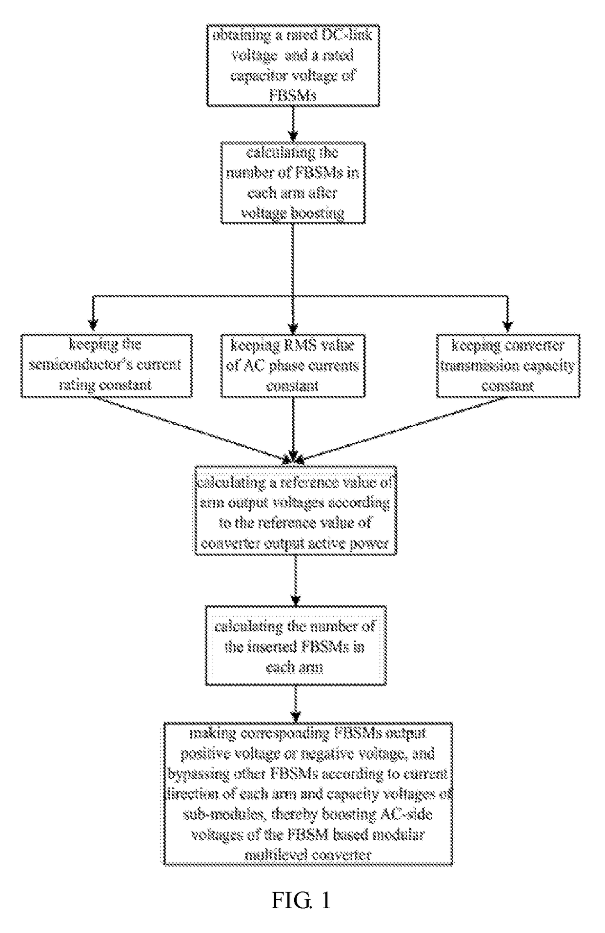
[0025]This embodiment is to illustrate advantages in improving transmission capacity of the converter and reducing converter cost while keeping RMS value of AC currents constant after AC-side voltage boosting. Quantitative analysis is give below for better understanding.

[0026]Firstly, the advantage of improving transmission capacity of a converter by boosting AC-side voltages is analyzed.

[0027]Transmission capacity of the converter S after AC-side voltage boosting can be expressed as

S=32UjmIjm,

where Ujm and Ijm are peak values of AC-side voltages and AC-side currents after AC-side voltage boosting respectively. Obviously, the transmission capacity of the converter will increase along with the increase of Ujm under a constant Ijm.

[0028]Next, advantage of reducing converter cost by boosting AC-side voltages is analyzed. Assuming the converter operates as a rectifier, take phase a for example, the instantaneous power flowing in the upper and lower arm can be expressed as:

{ppa=UdcIm[-m2...

embodiment 2

[0036]This embodiment is to illustrate advantages in reducing converter cost while keeping the semiconductor's current rating constant after AC-side voltage boosting. For better understanding, quantitative analysis is given in the following.

[0037]Assuming harmonic circulating currents are suppressed effectively, the RMS value of the arm current Ir can be expressed as:

Ir=√{square root over ((Idc / 3)2+(Im / 2√{square root over (5)})2)}

where Idc is the rated DC current and Im is peak value of AC-side currents.

[0038]Ignoring power loss of the converter, the relationship between Idc and Im can be expressed as:

Idc=34mImcosϕ,

where m is converter modulation index and ω is power factor angle.

[0039]Furthermore, the relationship between Im and Ir can be derived as:

Im=4Irm2cos2ϕ+2.

[0040]Similar to the analysis in embodiment 1, the relationship between the required capacitance value of FBSMs C and converter modulation index m under the constant semiconductor's current rating can be derived as:

C={Ir...

embodiment 3

[0042]This embodiment is to illustrate advantages in reducing converter cost further and improving operating efficiency of the converter while keeping transmission capacity of the converter constant after AC-side voltage boosting. For better understanding, quantitative analysis is given in the following.

[0043]Firstly, advantage of reducing converter cost is analyzed.

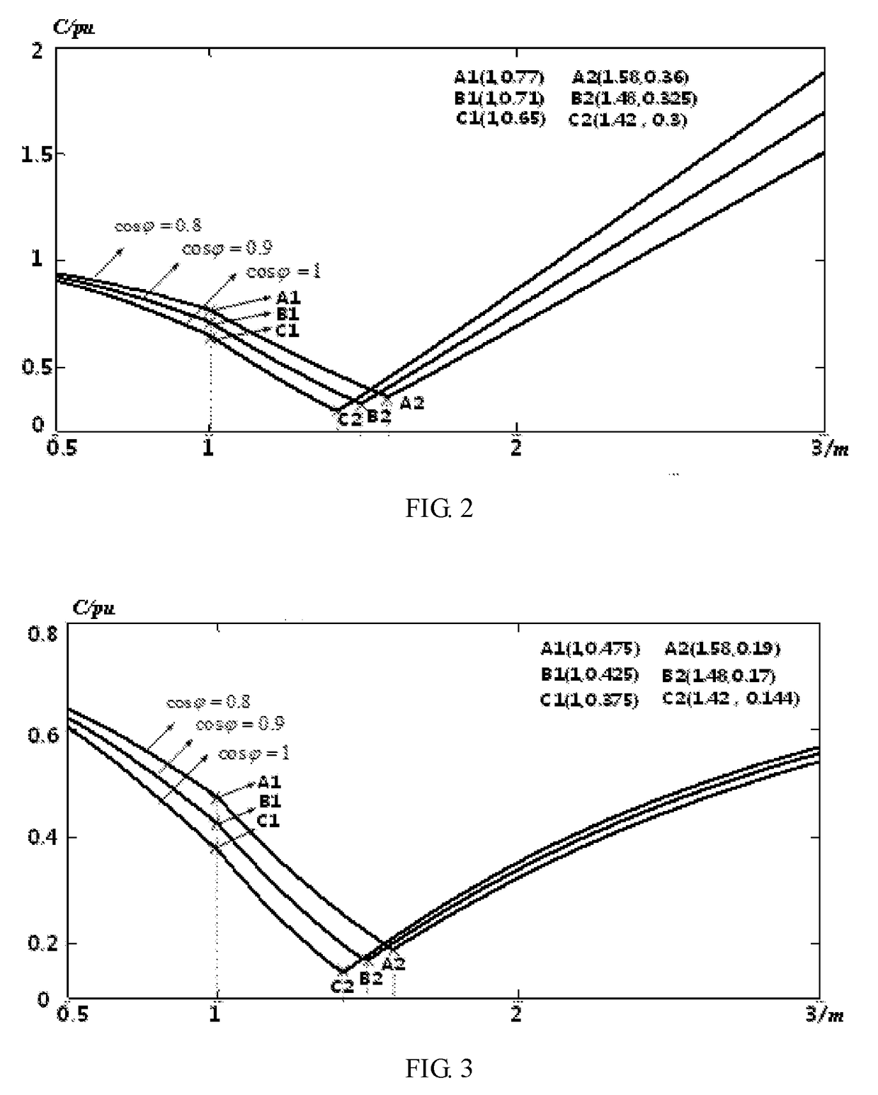
[0044]Similar to the analysis in embodiment 1 and embodiment 2, the relationship between the required capacitance value of FBSMs C and converter modulation index m under the constant transmission capacity can be derived as:

C={Idc3ɛUcω1mcosϕ[1-(mcosϕ2)2]1.5,m≤12Idc3ɛUcω1m(1+m)cosϕmax{[1-(mcosϕ2)2]1.5,m2cosϕ2(1-1m2)1.5},m>1,mcosϕ / 2<1Idc3ɛUcω1(1+m)m(1-1m2)1.5,mcosϕ / 2≥1.

[0045]FIG. 4 illustrates the relationships between the required capacitance value of FBSMs C and converter modulation index m with different power factors under the constant capacitor voltage ripple. Clearly, C decreases gradually along with the increas...


PUM


Abstract

Provided is an operating method of a full-bridge sub-module (FBSM)-based modular multilevel converter for HVDC transmission with AC-side voltage boosting. The peak value of the AC-side voltage is increased under a constant DC-link voltage by using FBSM's negative output voltage under steady state, wherein keeping the semiconductor's current rating constant during AC-side voltage boosting is in favor of reducing converter cost by decreasing energy interaction between the upper and lower arms in a leg, and further capacitance value of FBSM's capacitor under a constant capacitor voltage ripple, keeping the RMS value of AC-side current constant during AC-side voltage boosting can effectively improve transmission capacity of the converter while reducing converter cost, and keeping converter transmission capacity constant during AC-side voltage boosting can reduce RMS value of arm currents while reducing converter cost, thereby reducing power loss of FBSMs and improving converter efficiency.

Description

FIELD OF THE INVENTION[0001]The invention relates to a technical field of multilevel power electronic converters, and more particularly to an operating method of a full-bridge sub-module (FBSM)-based modular multilevel converter with AC-side voltage boosting.BACKGROUND OF THE INVENTION[0002]Modular multilevel converter (MMC) has been a competitive candidate for voltage source converter (VSC) based high voltage direct current (HVDC) transmission due to its advantages of avoiding IGBT series operation, improved scalability, high efficiency and excellent output waveforms with low harmonic distortion.[0003]At present, most of the VSC based HVDC projects adopt the half-bridge sub-module (HBSM) based MMC which cannot isolate a DC short fault and requires breakers on AC side or DC side for fast fault isolation. However, breakers on AC side can only clear the DC fault at the zero crossing point of AC-side current meaning considerable delay time existing before the breaker acts, and the DC s...

Claims


Application Information

Patent Timeline
IPC IPC(8): H02J3/36
CPCH02J3/36Y02E60/60H02M7/483H02M7/4835
Inventor HU, JIABINGLU, MAOZENGXIANG, MUCHAOLIN, LEI
Owner HUAZHONG UNIV OF SCI & TECH
Why Eureka
Try Eureka