Microfluidic apparatus having an optimized electrowetting surface and related systems and methods
What is Al technical title?
Al technical title is built by PatSnap Al team. It summarizes the technical point description of the patent document.
a microfluidic and electrowetting surface technology, applied in the direction of microorganism fixing/supporting apparatus, fluid controller, laboratory glassware, etc., can solve the problems of inability to scale or implement additional functionality, and the present solution for electrowetting is extremely limited in natur
Active Publication Date: 2017-06-22
PHENOMEX INC
View PDF2 Cites 26 Cited by
Summary
Abstract
Description
Claims
Application Information
AI Technical Summary
This helps you quickly interpret patents by identifying the three key elements:
Problems solved by technology
Method used
Benefits of technology
[0003]In one aspect, the invention provides a microfluidic device comprising an electrowetting configuration which includes a substrate having a droplet actuation surface, the droplet actuation surface comprising (or consisting of, or consisting essentially of) a hydrophobic layer (i.e., an outer hydrophobic layer) covalently bonded to the surface of an underlying dielectric layer (i.e., an inner dielectric layer). When the microfluidic device is operatively connected to a voltage source, an aqueous droplet resting upon or otherwise contacting the hydrophobic layer can be reliably and robustly wetted, and thereby moved, by an electrowetting force.
Problems solved by technology
Present solutions for electrowetting are extremely limited in nature and fail to scale or implement additional functionality.
Method used
Image
Click on the blue label to locate the original text in one second.
Reading with bidirectional positioning of images and text.
Examples
example 1
on of an Electrowetting Microfluidic Device Having Modified Interior Surfaces
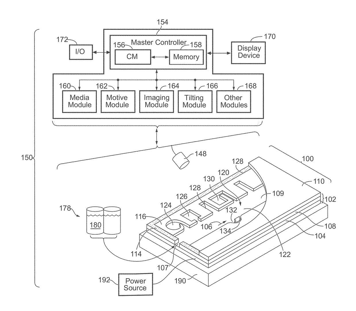
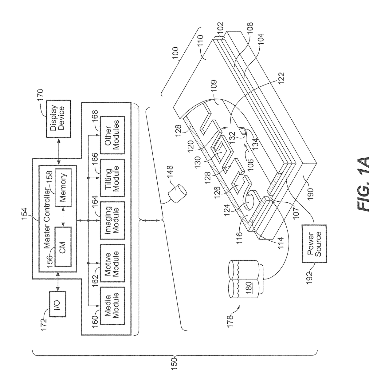
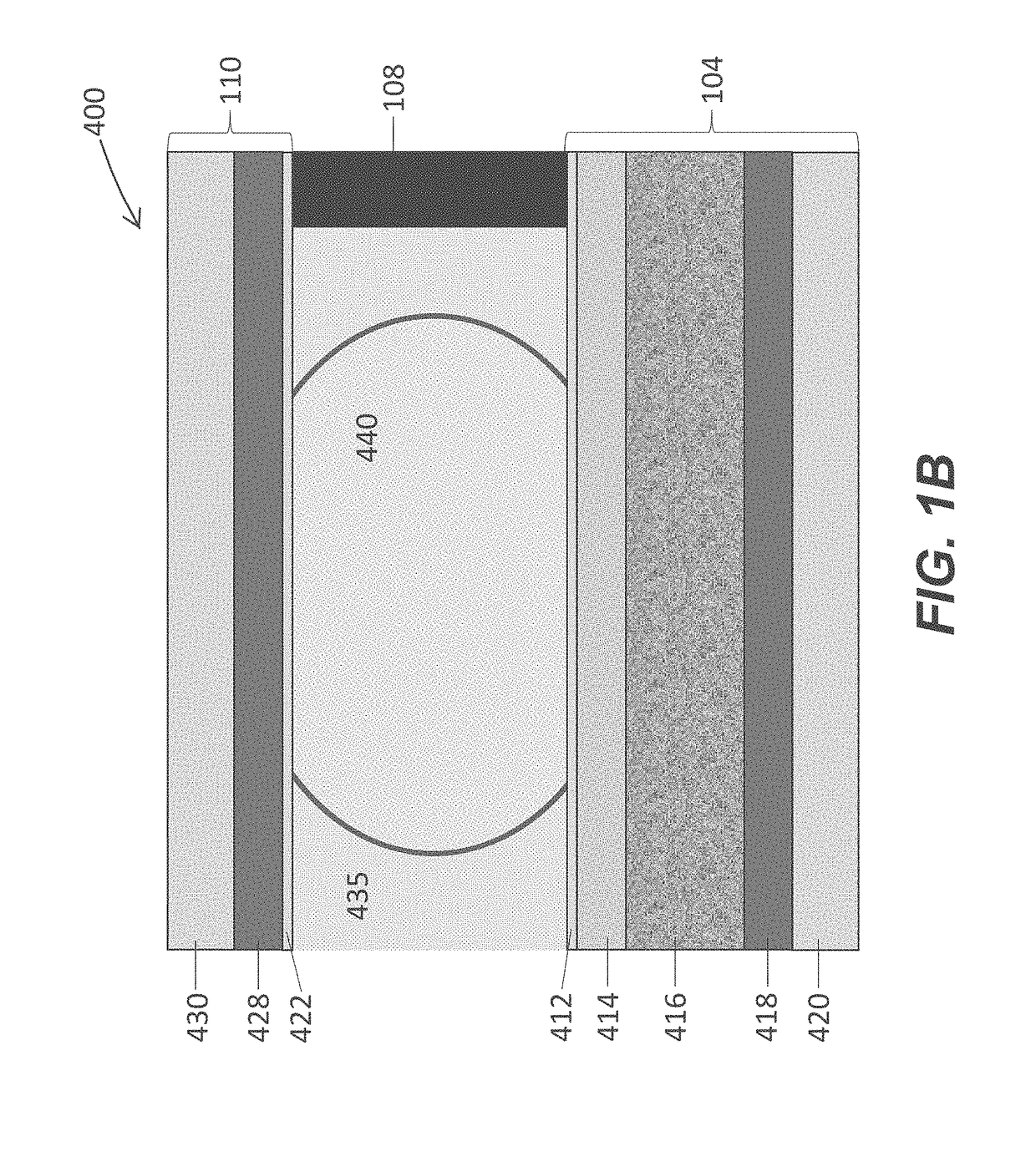
[0312]A microfluidic device (Berkeley Lights, Inc.) having a base that included an electrode activation substrate having a semiconductive layer of photosensitive silicon and a dielectric layer having an upper surface of alumina, a cover having a glass support with an ITO electrode, and microfluidic circuit material of photopatterned silicone separating the base and the cover, was treated in an oxygen plasma cleaner (Nordson Asymtek) for 1 min, using 100 W power, 240 mTorr pressure and 440 sccm oxygen flow rate. The plasma treated microfluidic device was treated in a vacuum reactor with trimethoxy (3, 3, 4, 4, 5, 5, 6, 6, 7, 7, 8, 8, 9, 9, 10, 10, 11, 11, 12, 12, 13, 13, 14, 14, 15, 15, 16, 16, 16)-nonaicosafluorohexadecyl)silane (0.3 g, details of synthesis as described in U.S. Provisional Application 62 / 410,238, filed Oct. 19, 2016) in a foil boat in the bottom of the vacuum reactor in the presence of magn...
PUM
Abstract
Microfluidic devices having an electrowetting configuration and an optimized droplet actuation surface are provided. The devices include a conductive substrate having a dielectric layer, a hydrophobic layer covalently bonded to the dielectric layer, and a first electrode electrically coupled to the dielectric layer and configured to be connected to a voltage source. The microfluidic devices also include a second electrode, optionally included in a cover, configured to be connected to the voltage source. The hydrophobic layer features self-associating molecules covalently bonded to a surface of the dielectric layer in a manner that produces a densely-packed monolayer that resists intercalation and or penetration by polar molecules or species. Also provided are microfluidic devices having an electrowetting configuration that further include a section or module having a dielectrophoresis configuration; systems that include any of the microfluidic devices in combination with an aqueous droplet and a fluidic medium immiscible with the medium of the aqueous droplet; related kits; and methods of manipulating droplets, optionally containing micro-objects such as biological cells, within the microfluidic devices.
Description
PRIORITY[0001]This application claims priority from U.S. provisional application No. 62 / 246,605, filed Oct. 27, 2015, U.S. provisional application No. 62 / 247,725, filed Oct. 28, 2015, U.S. provisional application No. 62 / 342,131, filed May 26, 2016, and U.S. provisional application No. 62 / 410,238, filed Oct. 19, 2016, the contents of each of which are incorporated herein by reference in their entirety. This application is a continuation-in-part of U.S. patent application Ser. No. 15 / 135,707, filed Apr. 22, 2016, the contents of which are incorporated herein by reference in their entirety.BACKGROUND[0002]Micro-objects, such as biological cells, can be processed in microfluidic apparatuses. For example, droplets containing micro-objects or reagents can be moved around and merged within a microfluidic apparatus. Embodiments of the present invention are directed to improvements in microfluidic apparatuses that facilitate robust manipulation of droplets, allowing complex chemical and biol...
Claims
Application Information
Patent Timeline
Application Date:The date an application was filed.
Publication Date:The date a patent or application was officially published.
First Publication Date:The earliest publication date of a patent with the same application number.
Issue Date:Publication date of the patent grant document.
PCT Entry Date:The Entry date of PCT National Phase.
Estimated Expiry Date:The statutory expiry date of a patent right according to the Patent Law, and it is the longest term of protection that the patent right can achieve without the termination of the patent right due to other reasons(Term extension factor has been taken into account ).
Invalid Date:Actual expiry date is based on effective date or publication date of legal transaction data of invalid patent.
Patent Type & Authority Applications(United States)