
Welding torch, welding robot, and welding system

a welding robot and welding technology, applied in the field of welding robots, welding welding systems, welding torches, etc., can solve the problems of increased accumulation speed of spatters, more frequent cleaning, and damage to the tip body

Active Publication Date: 2017-06-22
KOBE STEEL LTD
View PDF2 Cites 4 Cited by
  • Summary
  • Abstract
  • Description
  • Claims
  • Application Information

AI Technical Summary

Benefits of technology

The present invention provides welding torches with improved shielding performance and resistance to spatter adhesion. The torches were tested by repeatedly performing continuous welding and automatic cleaning for one hour, 10 times in total. The conditions of the test are described in detail, and the results show that the torches can effectively shield the welding process and maintain their operability. The technical effects of the invention include improved weld quality, efficiency, and durability.

Problems solved by technology

However, there has been a possibility that in the welding torch disclosed in abovementioned JP 2014-233723 A, spatters may enter between the contact tip and the orifice-member support nut so that the accumulation speed of spatters may increase, and upon detachment or attachment of the contact tip and the orifice-member support nut, spatters may be bitten between their threaded portions so that the tip body may be damaged.
With the nozzle cleaning device disclosed in abovementioned JP H05-138361 A, on the other hand, the removal of spatters, which have entered between the contact tip and the orifice-member support nut, is difficult, resulting in more frequent cleaning.
This has remained as an impediment to the automatic operation of a welding machine.
Further, there has been a possibility that the more frequent cleaning may lead to increased wear of the brushes so that the frequency of replacement of the brushes may become higher and the welding costs may increase.
In addition, it has hitherto not been a practice to dispose, in the nozzle, a member for blocking spatters that fly from a front end of the contact tip, because such a member may disturb the flow of shielding gas through the nozzle to cause shielding failure.

Method used


Image

  • Welding torch, welding robot, and welding system
  • Welding torch, welding robot, and welding system
  • Welding torch, welding robot, and welding system

Examples


examples

[0075]To confirm advantageous effects of the present invention, welding torches including the shield members of Examples 1-8 and Comparative Examples 1-3 as indicated in Table 1 were provided, and were each then subjected to a welding test. In that test, continuous welding for one hour and automatic cleaning (contact tip replacement, nozzle cleaning) were repeatedly performed 10 times (10 hours in total), and shielding performance with shielding gas, continuous automatic operability, and resistance to spatter adhesion were checked.

[0076]Next, welding conditions in that test will be described. Note that the welding conditions to be described herein are illustrative, and the embodiment of the present invention should not be limited to the following welding conditions.

[0077]Welding Conditions

[0078]Welding current: 300 A

[0079]Arc voltage: 32 V

[0080]Welding speed: 30 cm / min

[0081]Wire extension: 25 mm

[0082]Shielding gas: 100% CO2 gas

[0083]Outer diameter of orifice member: 14 mm

[0084]Front...


PUM

PropertyMeasurementUnit
Raaaaaaaaaaa
thicknessaaaaaaaaaa
thicknessaaaaaaaaaa

Abstract

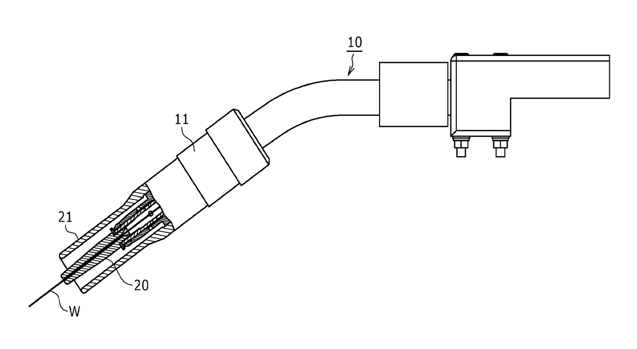
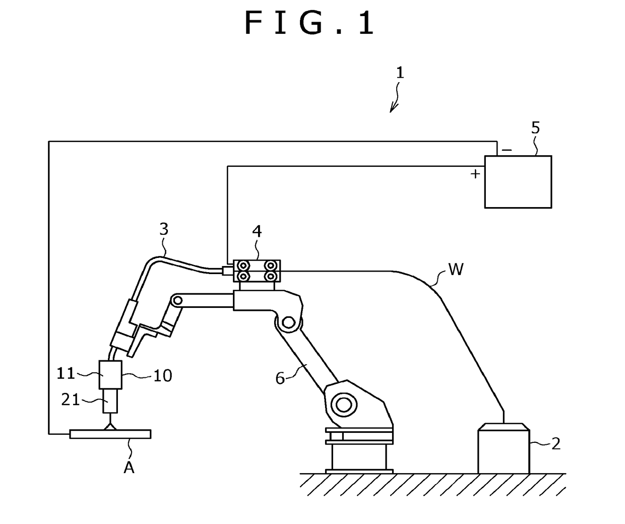
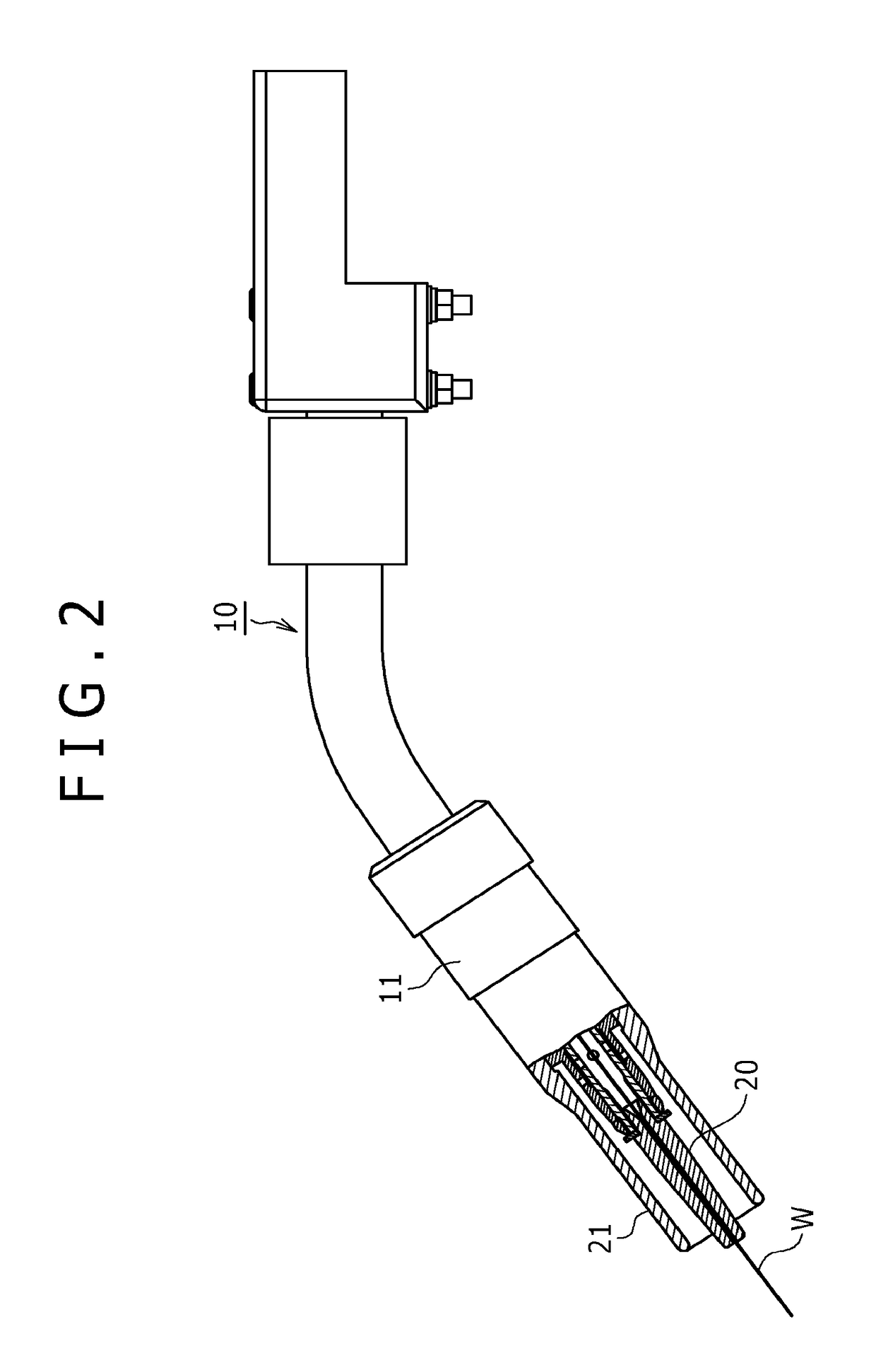
A tip attached to a torch barrel of a welding torch includes: a cylindrical tip body attached to the torch barrel; a cylindrical orifice member fitted on an outer circumference of the tip body; an orifice-member support nut detachably attached to a front end outer circumference of the tip body and supporting the orifice member on the outer circumference of the tip body; a cylindrical contact tip detachably attached to a front-end inner circumference of the tip body; and an annular shield member disposed between the tip body and the contact tip. The shield member has an outer diameter set no less than a front-end outer diameter of the orifice-member support nut but no more than an outer diameter of the orifice member. A welding robot including the welding torch and a welding system including the welding robot and a welding power supply are also disclosed.

Description

BACKGROUND OF THE INVENTION[0001]Field of the Invention[0002]The present invention relates to a welding torch, a welding robot, and a welding system to be used for gas-shielded arc welding.[0003]Description of the Related Art[0004]As conventional welding torches, there are known those provided with a cylindrical tip body connected to a torch barrel, a cylindrical orifice member fitted on an outer circumference of the tip body from a front end side of the tip body, an orifice-member support nut detachably provided on a front-end outer circumference of the tip body and supporting the orifice member on the tip body, and a cylindrical contact tip detachably provided at a front end of the tip body (for example, see JP 2014-233723 A).[0005]Moreover, hitherto, there are known nozzle cleaning devices for a welding torch that remove spatters, which have adhered on an inner circumferential surface of a nozzle of such a welding torch and an outer circumferential surface of a tip, by inserting ...

Claims


Application Information

Patent Timeline
Patent Type & Authority Applications(United States)
IPC IPC(8): B23K9/29B23K9/32B23K9/173
CPCB23K9/295B23K9/321B23K9/173B23K9/164B23K9/26B23K9/28B23K9/325B23K9/328
Inventor TAKEMURA, YOSHIYATAKADA, SHIGETO
Owner KOBE STEEL LTD
Learn More