Variable Refrigerant Package

a refrigerant package and variable technology, applied in space heating and ventilation, heating types, lighting and heating equipment, etc., can solve the problems of unit not running long enough, motels/hotels have a tendency to have a musty smell, and the wall units such as ptacs/vpacs have some basic problems, so as to reduce the amount of outside noise and reduce power consumption

Active Publication Date: 2017-06-22
FRIEDRICH AIR CONDITIONING LLC
View PDF10 Cites 21 Cited by
  • Summary
  • Abstract
  • Description
  • Claims
  • Application Information

AI Technical Summary

Benefits of technology

[0012]It is another object of the present invention to provide effective dehumidification of a conditioned space using a variable refrigerant package.
[0013]It is still another object of the present invention to provide variable, yet stable, power to the power consuming parts of a variable refrigerant package.
[0019]It is another object of the present invention to use pulse width modulation on the compressor and motors contained within a variable refrigerant package, which pulse width modulation is used to slowly bring the variable refrigerant package slowly to the inside temperature set in the room sensor to allow for increased dehumidification of the inside air.
[0021]It is a further object of the present invention to actively control the power factor of the variable refrigerant package for reduced power consumption.
[0022]It is another object of the present invention to reduce the amount of outside noise that reaches conditional space while simultaneously dehumidifying outside air being introduced to the conditional space.

Problems solved by technology

Through-the-wall units such as PTACs / VPACs have some basic problems.
For example, in coastal areas, motels / hotels have a tendency to have a musty smell due to the humidity.
The problem is the unit does not run long enough to remove the moisture from the space being conditioned.
Yet, building codes require ventilation of the areas being conditioned which PTAC / VPAC units do not normally provide.
Each of these systems are either complicated, expensive, or do not work properly.
However, this method requires the running of additional duct work and having a dehumidifier to remove moisture from the outside air.
However, the outside air was not dehumidified which adds humidity to the space and would many times cause a musty smell inside of the room.
Still, the variable refrigerant flow systems continue to have problems with high humidity and lack of available ventilation air.

Method used


Image

  • Variable Refrigerant Package
  • Variable Refrigerant Package
  • Variable Refrigerant Package

Examples


Embodiment Construction

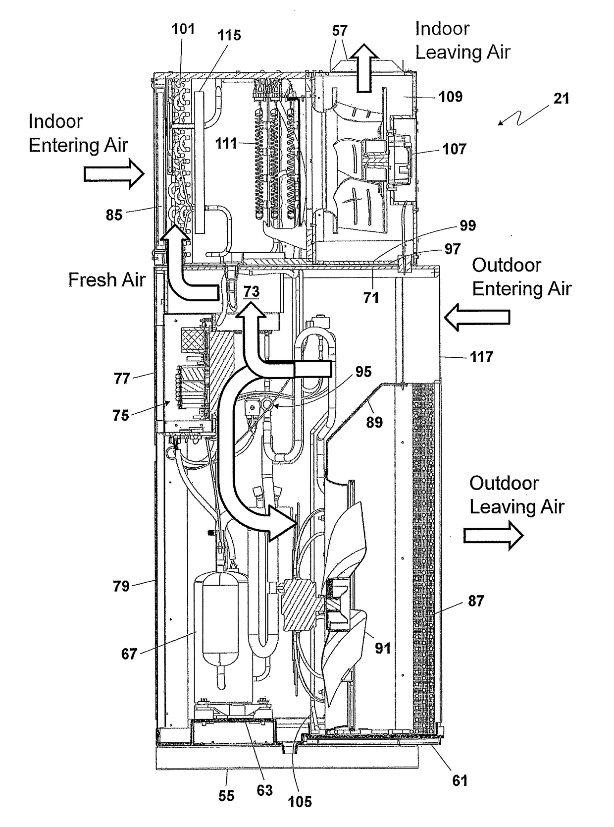
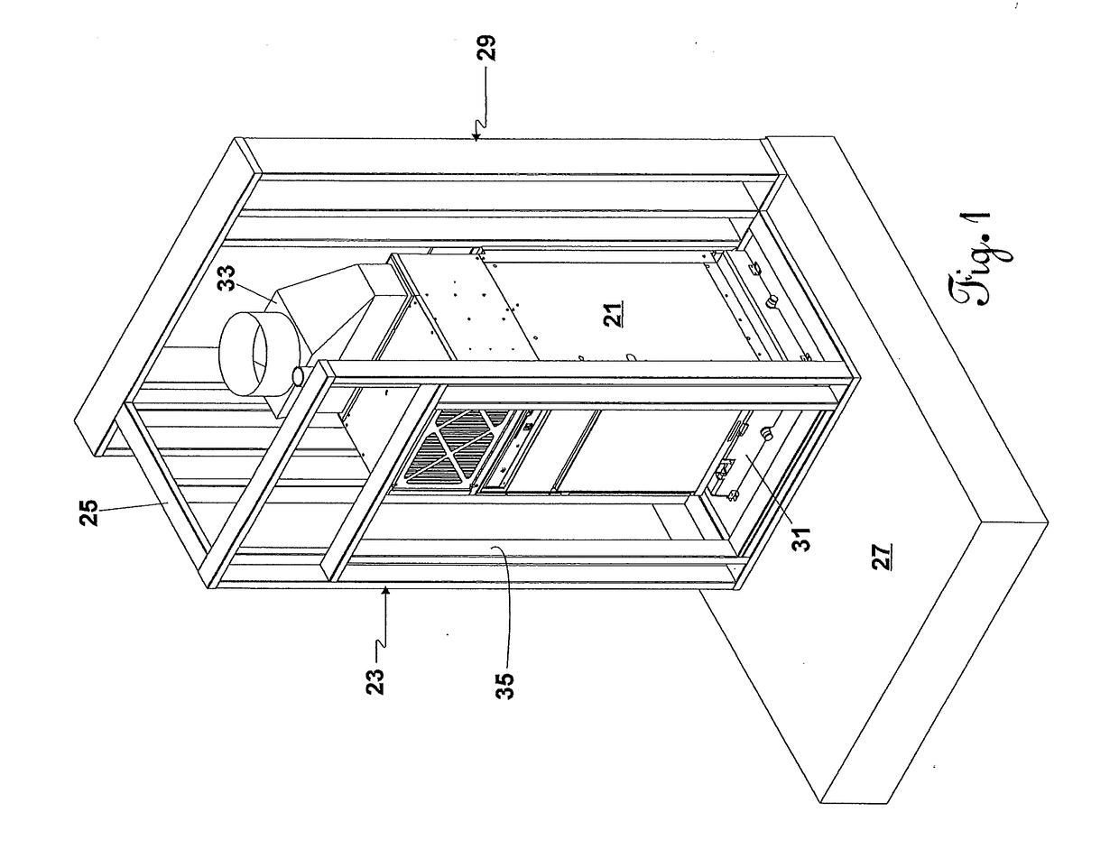
[0036]A preferred embodiment of the present invention will be given herein below in conjunction with the illustrations shown in the attached figures. A variable refrigerant package 21 is shown in FIG. 1 installed in a closet 23 formed by frame 25 on floor 27 of a space to be cooled. Frame 25 extends to the outside 29 of the space being cooled. For illustration purposes, the sheetrock or other covering material for the frame 25 has been removed.

[0037]Inside of the closet 23 is installed a base 31 on which the variable refrigerant package 21 sits. A duct adapter 33 is installed near the top of the closet 23 for connection to the top of the variable refrigerant package 21 to direct the conditioned air to a desired location. The variable refrigerant package 21 is inserted into the closet 23 through door opening 35.

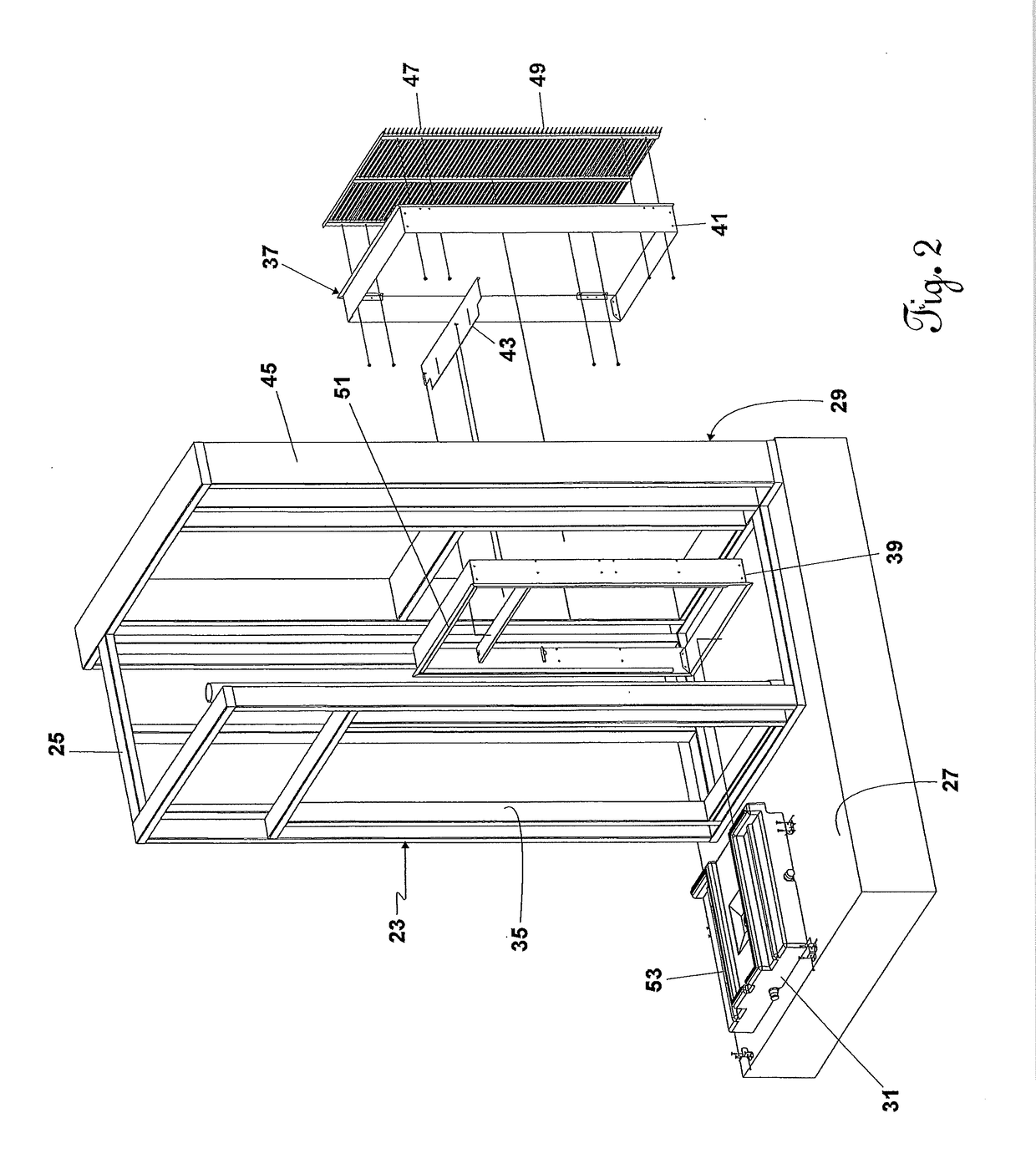
[0038]Referring now to FIG. 2, the variable refrigeration package 21 has been removed. During construction of the closet 23 by the contractor building the hotel / motel, a plenu...


PUM


Abstract

A variable refrigerant package air conditioner is shown that is easy to install in new construction with a unique base that causes collected mixture that overflows to drain outside the building. A control system is shown that has motors and compressor that are pulse width modulated so the air conditioner is infinitely variable while maintaining the highest possible power factor. Dehumidification of outside air occurs as it is mixed with inside air. By gradually approaching a temperature set point and even reheating after dehumidification, moisture is removed from the room. A snorkel that delivers fresh air to be mixed with inside entering air in front of the evaporator for a maximum dehumidification is also shown.

Description

CROSS-REFERENCE TO RELATED APPLICATIONS[0001]This application is a continuation-in-part of application Ser. No. 14 / 975,166, filed Dec. 18, 2015.BACKGROUND OF THE INVENTION[0002]1. Field of the Invention[0003]This invention relates to a variable refrigerant package (VRP), and more particularly, to a packaged terminal air conditioner that dehumidifies outside air added to air conditioned room, the outside air being added through a sound dampening snorkel.[0004]2. Description of the Prior Art[0005]A package terminal air conditioner (PTAC) and a vertical packaged air conditioner (VPAC) are types of self-contained heating and air conditioning systems commonly found in hotels or motels. Most PTAC and VPAC units are designed to go through a wall having vents and / or heat sinks both inside and outside. While PTACs and VPACs are commonly used to heat or cool a single living space, there are cooling only PTACs and / or VPACs with an external heating source. On some PTACs / VPACs condensate drain p...

Claims


Application Information

Patent Timeline
Patent Type & Authority Applications(United States)
IPC IPC(8): F24F1/02F24F13/28F24F13/22F24F13/24
CPCF24F13/24F24F13/28F24F13/222F24F1/027F24F2221/34F24F2203/021F24F2013/242F24F3/1405F24F3/153F24F11/56
Inventor EICHER, KEVIN L.CAGLE, GEORGE C.GUERRERO, EDUARDO J.COTNER, BASCOM CLAYTON
Owner FRIEDRICH AIR CONDITIONING LLC
Why Eureka
Try Eureka