Single and multi-stage high power optical isolators using a single polarizing element

a technology of optical isolators and polarizing elements, applied in the direction of mirrors, instruments, polarising elements, etc., can solve the problems of high transmission loss of reverse propagation radiation, and achieve the effects of preventing optical damage in the optical elements, reducing the number of optical parts, and simple alignmen

Inactive Publication Date: 2017-06-22
ELECTRO OPTICS TECH
View PDF4 Cites 7 Cited by
  • Summary
  • Abstract
  • Description
  • Claims
  • Application Information

AI Technical Summary

Benefits of technology

[0011]The present invention provides PM and PI multi-pass isolator forms that are simple to align, have few optical parts to assemble and work well with scalable beam diameters large enough to prevent optical damage in the optical elements of the isolator when used with high peak and average power laser sources. The present invention relates to high peak and average power optical isolators and more particularly to high power single and multi-stage polarization maintaining [“PM”] and polarization insensitive [“PI”] optical isolators with improved size, improved alignment simplicity, reduced parts count, and reduced cost.

Problems solved by technology

This results in reverse propagating radiation to experience high transmission losses while allowing forward propagating radiation to experience low transmission losses.

Method used


Image

  • Single and multi-stage high power optical isolators using a single polarizing element
  • Single and multi-stage high power optical isolators using a single polarizing element
  • Single and multi-stage high power optical isolators using a single polarizing element

Examples


Embodiment Construction

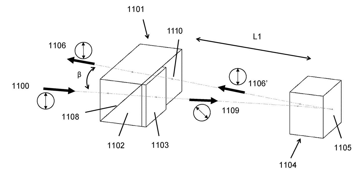
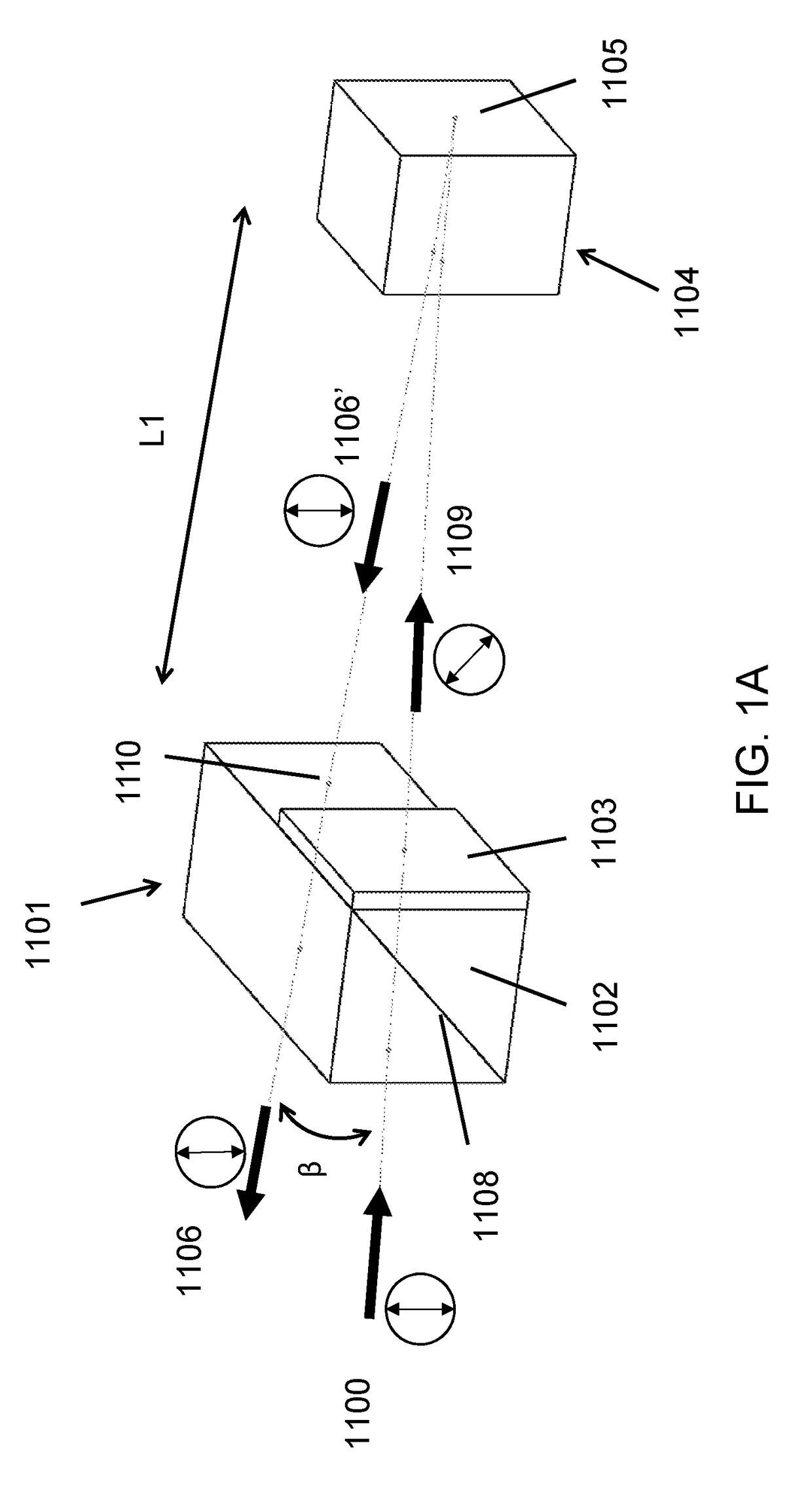
[0028]Referring now to the drawings and the illustrative embodiments depicted therein, FIG. 1A is a perspective view of a PM single stage, dual pass isolator for generally collimated laser radiation that is comprised of only two separate optical components in accordance with the invention. Collimated laser radiation source 1100 with substantially linear p polarization is incident upon single polarization element 1101 comprised of quartz half-waveplate 1103 bonded, such as by adhesive free optical contact, to fused silica PBS 1102. The optic axis of half-waveplate 1103 is rotated by an angle of 22.5 degrees with respect to the original linear p polarization axis (shown as vertical in FIG. 1A), such that highly polarized p polarization transmitted through polarizing coating 1108 is rotated by +45 degrees of reciprocal rotation in half-waveplate 1103 as shown by the circled polarization state arrow 1109.

[0029]Laser radiation at 1109 is then incident upon Faraday optic 1104 (such as a T...


PUM

PropertyMeasurementUnit
magnetic fieldaaaaaaaaaa
birefringentaaaaaaaaaa
magnetic field strengthaaaaaaaaaa

Abstract

An optical isolator for generally collimated laser radiation includes a single polarizing element, at least one Faraday optical element, at least one reciprocal polarization altering optical element disposed at the single polarizing element, at least one reflective optical element for reflecting radiation to provide an even number of passes through the at least one Faraday optical element, and a magnetic structure. The magnetic structure is capable of generating a magnetic field within the at least one Faraday optical element that is generally aligned with the even number of passes along a beam propagation axis. The optical isolator is configured to receive generally collimated laser radiation, which passes through the single polarizing element and the at least one reciprocal polarization altering optical element and which makes at least two passes through the at least one Faraday optical element, whereby generally collimated laser radiation is output from the optical isolator.

Description

CROSS REFERENCE TO RELATED APPLICATION[0001]The present application claims the filing benefits of U.S. provisional application Ser. No. 62 / 269,349, filed Dec. 18, 2015, which is hereby incorporated herein by reference in its entirety.FIELD OF THE INVENTION[0002]The present invention relates to high power optical isolators and more particularly to high power single and multi-stage polarization maintaining [“PM”] and polarization insensitive [“PI”] optical isolators.BACKGROUND OF THE INVENTION[0003]Optical isolators are routinely used to decouple a laser oscillator from downstream laser amplifier noise radiation and / or target reflections. Optical isolators are typically comprised of a Faraday rotator surrounded by polarizers that are aligned with the input and output linear polarization states. A Faraday rotator is typically comprised of a non-reciprocal, optical element in a strong magnetic field that is co-axially aligned with the laser radiation so that the plane of polarization is...

Claims


Application Information

Patent Timeline
Patent Type & Authority Applications(United States)
IPC IPC(8): G02F1/09G02B5/30G02B5/08G02B27/28
CPCG02F1/093G02B27/286G02B5/3083G02B5/0808G02B5/3025
Inventor SCERBAK, DAVID G.ROGERS, EVANROUDSAR, AMIR JALALIMAMBOURG, JOSEPH R.
Owner ELECTRO OPTICS TECH
Why Eureka
Try Eureka