
Compact inductor

Active Publication Date: 2017-06-22
ROCKWELL AUTOMATION TECH
View PDF8 Cites 4 Cited by
  • Summary
  • Abstract
  • Description
  • Claims
  • Application Information

AI Technical Summary

Benefits of technology

The patent text describes a new type of inductor that can be placed in smaller spaces and can be cooled using passive means. This makes it easier and cheaper to use the inductor in power supplies and other electrical devices. The technical effect of this patent is to provide a more efficient and cost-effective solution for incorporating inductors into electrical devices.

Problems solved by technology

In addition, the magnetic flux generated by an inductor often makes it difficult to cool the inductor using passive means such as cooling fins.

Method used


Image

  • Compact inductor
  • Compact inductor
  • Compact inductor

Examples


Embodiment Construction

[0035]Reference throughout this specification to “one embodiment,”“an embodiment,” or similar language means that a particular feature, structure, or characteristic described in connection with the embodiment is included in at least one embodiment. Thus, appearances of the phrases “in one embodiment,”“in an embodiment,” and similar language throughout this specification may, but do not necessarily, all refer to the same embodiment, but mean “one or more but not all embodiments” unless expressly specified otherwise. The terms “including,”“comprising,”“having,” and variations thereof mean “including but not limited to” unless expressly specified otherwise. An enumerated listing of items does not imply that any or all of the items are mutually exclusive and / or mutually inclusive, unless expressly specified otherwise. The terms “a,”“an,” and “the” also refer to “one or more” unless expressly specified otherwise.

[0036]The schematic flowchart diagrams and / or schematic block diagrams in th...


PUM


Abstract

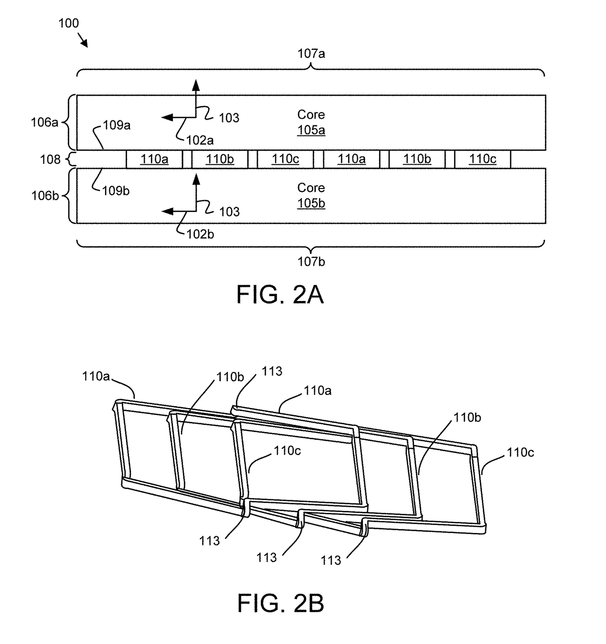
For reducing volume requirements and magnetic flux leakage, a compact inductor includes a first planar core with a first core thickness along a first axis orthogonal to a plane of the first planar core. In addition, the inductor includes a second planar core disposed parallel to the first planar core with a second core thickness along the first axis. The inductor further includes a plurality of electrical windings disposed between and adjacent to an inside plane of the first planar core and an inside plane of the second planar core. The electrical windings may include insulated electrical wires. No magnetic teeth may be disposed between the first planar core and the second planar core. The first axis is parallel to a magnetic axis of each electrical winding.

Description

FIELD[0001]The subject matter disclosed herein relates to inductors and more particularly relates to a compact inductor.BACKGROUND INFORMATION[0002]Inductors are widely used electrical components.BRIEF DESCRIPTION[0003]Inductors are commonly used in electrical devices and are often included in power supplies. Because inductors generate magnetic flux and / or electromagnetic radiation, inductors must often be physically separated from other components in a chassis. In addition, the magnetic flux generated by an inductor often makes it difficult to cool the inductor using passive means such as cooling fins. A compact inductor is disclosed that reduces the leakage of magnetic flux and electromagnetic radiation so that the inductor may be disposed within a smaller volume. In addition, the inductor may support the use of passive cooling, further reducing the operating costs of employing the inductor.[0004]The inductor includes a first planar core with a first core thickness along a first a...

Claims


Application Information

Patent Timeline
IPC IPC(8): H01F27/08H02M7/02H01F27/28
CPCH01F27/085H02M7/02H01F27/2823H01F3/10H01F27/306
Inventor SUN, XIKAIQIAN, WEIZHANG, SHAOFENGLU, HAIHUIWEI, LIXIANGXIAO, YUANHU, JIANGANGLUKASZEWSKI, RICHARD A.
Owner ROCKWELL AUTOMATION TECH
Learn More