Active Filter Device and Circuit Arrangement Comprising an Active Filter Device

Active Publication Date: 2017-06-22
TDK ELECTRONCS AG
View PDF3 Cites 5 Cited by
  • Summary
  • Abstract
  • Description
  • Claims
  • Application Information

AI Technical Summary

Benefits of technology

[0012]Embodiments of the inventio

Problems solved by technology

For instance, on motor drive output lines, earth leakage current can result in a rapid degradation of motor bearings.
In order to achieve the desired attenuation, the passive elements are often large and

Method used


Image

  • Active Filter Device and Circuit Arrangement Comprising an Active Filter Device
  • Active Filter Device and Circuit Arrangement Comprising an Active Filter Device
  • Active Filter Device and Circuit Arrangement Comprising an Active Filter Device

Examples


Embodiment Construction

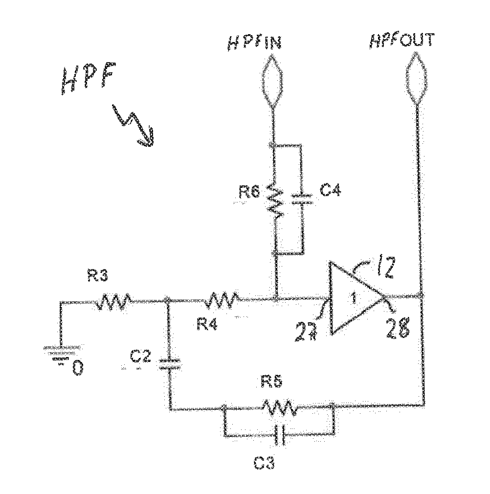
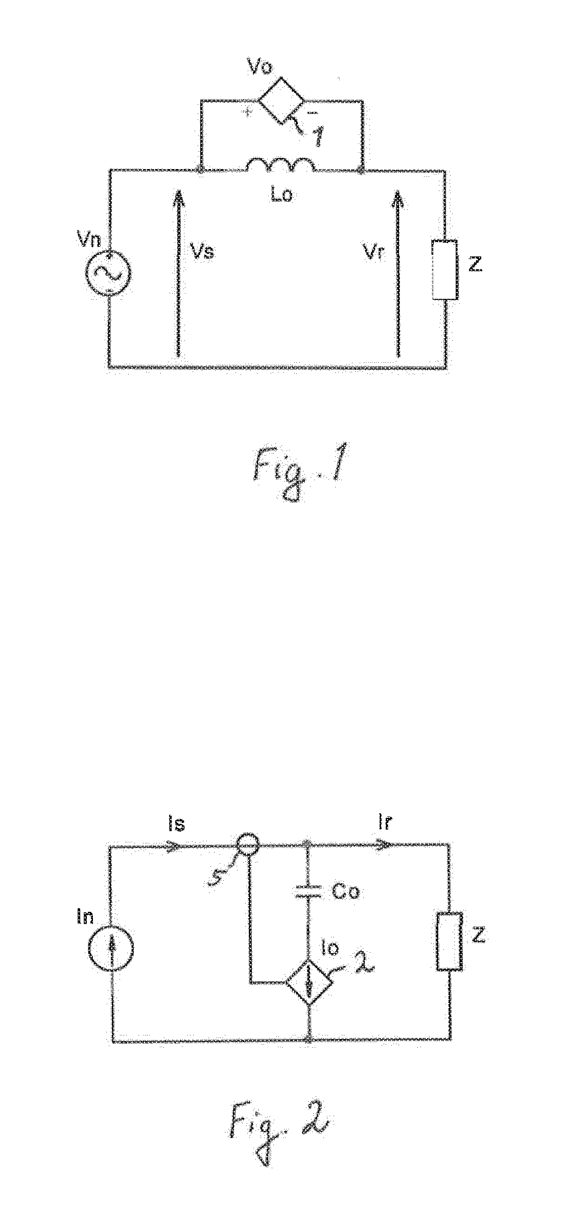
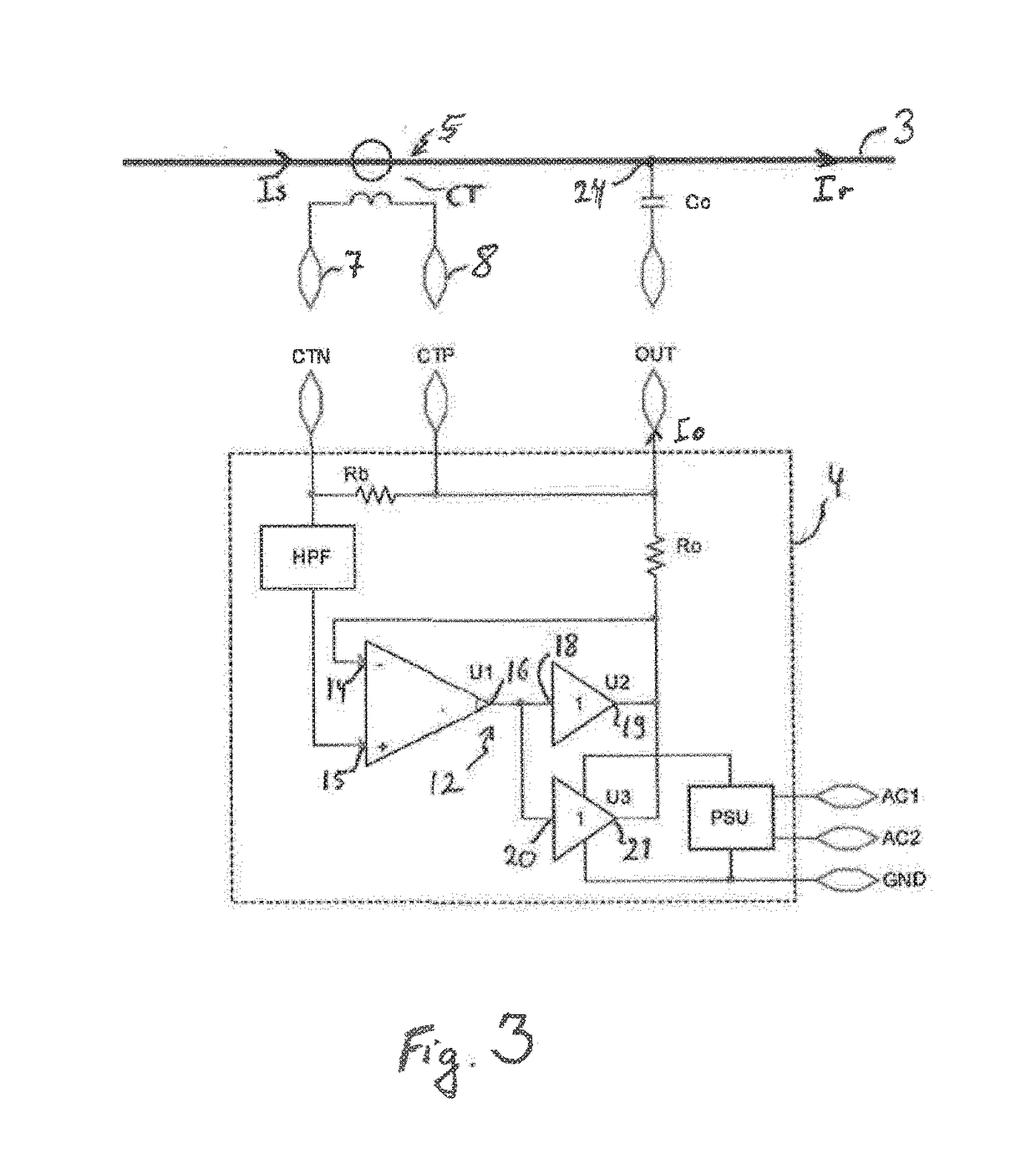
[0039]FIGS. 1 and 2 illustrate the method of filtering operation, which works in principle as follows. The disturbance on a power line, which is a noise signal, is detected by a sensing device which passes a sensor signal, via a high pass filter, to an amplifying device serving as the signal source. It produces an output signal serving as a correction signal which, over a designated bandwidth, has very nearly the same phase and magnitude as that detected by the sensing device. This can be described as a unity-gain feed-forward control path, wherein the gain is unity. Feed-forward is a term describing passing a controlling signal from a source to a load. A control system that has only feed-forward behaviour responds to its control signal in a pre-defined way without responding to how the load reacts.

[0040]The inverse of the output signal is summed with the sensed signal at, or over, a suitable summing point, or component, on the power line. The resulting signal on the power line, aft...


PUM


Abstract

An active filter device and a circuit arrangement comprising an active filter device are disclosed. In an embodiment the active filter device includes sensor terminals for applying a sensor signal depending on a sensed noise signal, an output terminal for providing a correction signal that is suitable for reducing the noise signal, a signal source adapted for generating a correction signal and a high-pass filter coupled between the sensor terminals and the signal source, wherein the correction signal is generated with a dependence on a high-pass filtered sensor signal.

Description

[0001]This patent application is a national phase filing under section 371 of PCT / EP2015 / 059182, filed Apr. 28, 2015, which claims the priority of European patent application 14167918.3, filed May 12, 2014, each of which is incorporated herein by reference in its entirety.TECHNICAL FIELD[0002]The present invention is directed to an active filter device. The invention is further directed to a filtering circuit arrangement including the active filter device. The filtering circuit arrangement may serve as a power line filter, which may be connected between a power supply network and an electrically operated appliance.BACKGROUND[0003]Filters may be used on power lines for the mitigation of electromagnetic noise, or earth leakage current, which may be generated by switching frequencies, for example.[0004]For instance, on motor drive output lines, earth leakage current can result in a rapid degradation of motor bearings.[0005]In many applications, a system switching frequency exists in th...

Claims


Application Information

Patent Timeline
IPC IPC(8): H03H11/12H02K11/02
CPCH02K11/02H03H11/126H02M1/12H02M1/44
Inventor TUCKER, ANDREW
Owner TDK ELECTRONCS AG
Why Eureka
Try Eureka