Rotary type wheel deburring device

a technology of deburring device and rotary type, which is applied in the direction of grinding drive, grinding machine components, manufacturing tools, etc., to achieve the effects of high degree of automation, simple structure and rapid removal

Active Publication Date: 2017-06-29
CITIC DICASTAL
View PDF4 Cites 17 Cited by
  • Summary
  • Abstract
  • Description
  • Claims
  • Application Information

AI Technical Summary

Benefits of technology

[0009]During actual use, a wheel reaches middle positions of four clamping wheels, the clamping cylinder enables the four clamping wheels to clamp the wheel and separate the wheel from a roller way surface through the upper gears and the gear racks, and the servo motor I enables the wheel to rotate in a clamped state; the servo motor II enables the brush to rotate, the servo electric cylinder I is used for adjusting the brush to an appropriate position through the guide rails II, then, the lifting cylinders are used for jacking up the brush through the guide posts, burrs of root corners of flanges can be removed when the brush is in contact with the root corners of the flanges, and burrs of roots of rims can be removed after the servo electric cylinder II is used for adjusting the brush to an appropriate horizontal angle through the guide rail III; and the servo motor III can be used for adjusting the brush to an appropriate angle in the circumferential direction through the lower gear and the geared ring, meanwhile, the servo electric cylinder III is used for adjusting the brush to an appropriate position through the guide rails I, the brush is enabled to rotate along a tangential direction of rotation of burrs of root included angles of the flanges, and the burrs of the root included angles of the flanges can be rapidly removed when the brush is in contact with the burrs of the root included angles of the flanges.
[0010]When in use, the rotary type wheel deburring device can be used for rapidly adjusting the angles of the horizontal and circumferential directions of the brush and can be used for carrying out targeted processing on the burrs of the focal parts; and meanwhile, the rotary type wheel deburring device has the characteristics of simple structure, high degree of automation, advanced technology, high universality, high efficiency and safe and stable performance.

Problems solved by technology

At present, the wheel deburring mode is that two rotary disc brushes, i.e., an upper rotary disc brush and a lower rotary disc brush are used for removing burrs of a front surface and a back cavity separately; and this mode has a still permissible effect on a majority of wheel types, however, for some wheel types with high requirements and some wheel types with complicated shapes, some parts cannot meet requirements due to this removal mode, so that aiming at shape characteristics of wheel windows, multifunctional deburring equipment is required to be researched and developed, thereby carrying out focused processing on the parts with difficult-to-remove burrs.

Method used


Image

  • Rotary type wheel deburring device
  • Rotary type wheel deburring device
  • Rotary type wheel deburring device

Examples


Embodiment Construction

[0018]In the following, the details and working conditions of a specific device provided by the present invention are described in combination with the figures.

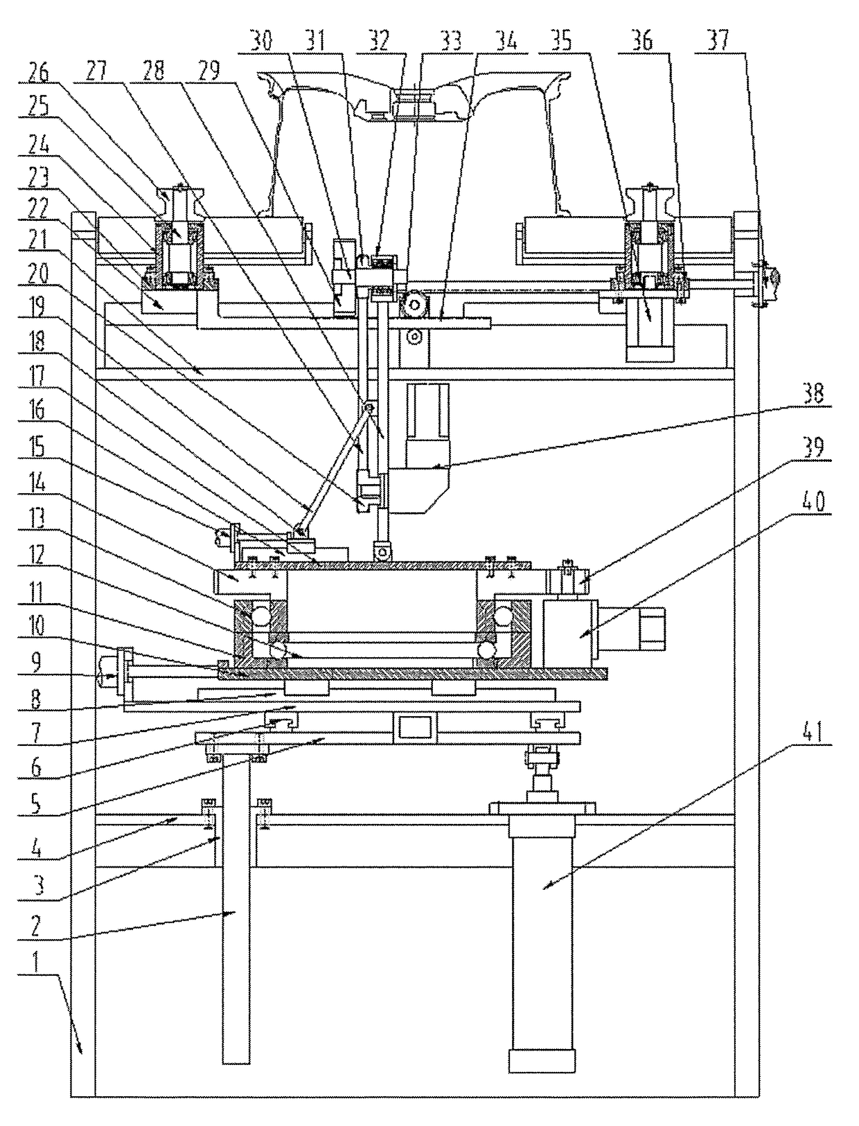
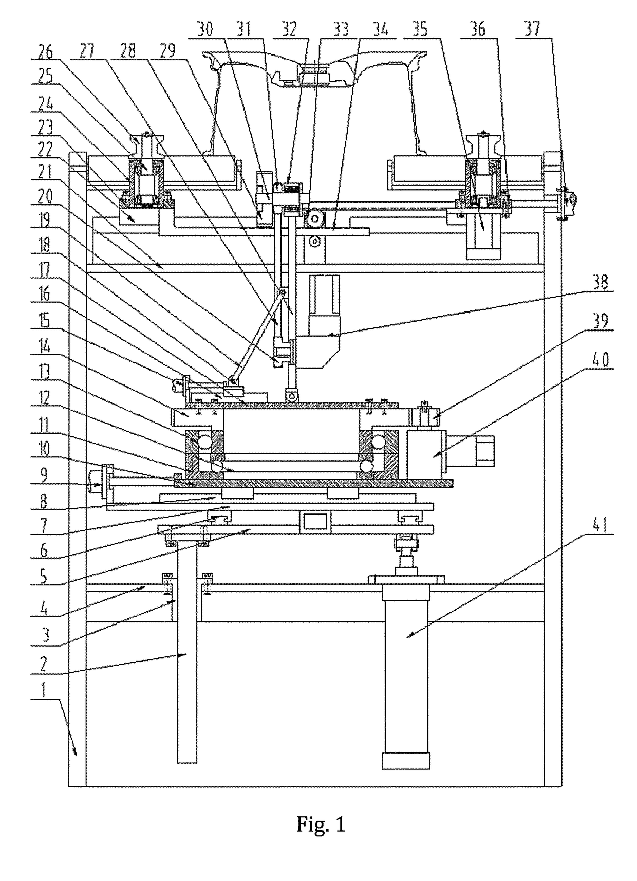
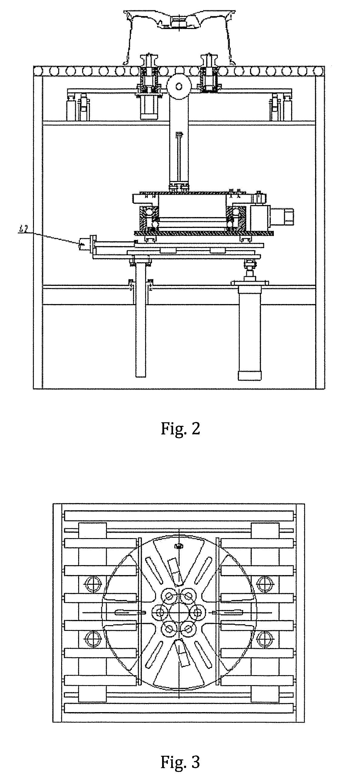
[0019]A rotary type wheel deburring device is composed of a machine frame 1, guide posts 2, guide sleeves 3, a bottom plate 4, a rising and falling plate 5, guide rails I 6, a lower sliding plate 7, guide rails II 8, a servo electric cylinder I 9, an upper sliding plate 10, lower bearing blocks 11, thrust bearings 12, revolving rings 13, a geared ring 14, a servo electric cylinder II 15, a guide rail III 16, a top plate 17, a sliding block 18, a link 19, a lower belt pulley 20, a supporting plate 21, an upper guide rail 22, a left sliding plate 23, upper bearing blocks 24, shafts I 25, clamping wheels 26, a synchronizing belt 27, a flipping plate 28, a brush 29, a shaft II 30, an upper belt pulley 31, a minor bearing block 32, upper gears 33, gear racks 34, a servo motor I 35, a right sliding plate 36, a clamping cylinder 37,...


PUM


Abstract

The present invention relates to a rotary type wheel deburring device, which comprises servo motors, cylinders, a brush, etc. When in use, a wheel reaches middle positions of four clamping wheels, a clamping cylinder enables the four clamping wheels to clamp the wheel and separate the wheel from a roller way surface through upper gears and gear racks, and a servo motor I enables the wheel to rotate in a clamped state; a servo motor II enables the brush to rotate; and a servo motor III can be used for adjusting the brush to an appropriate angle in the circumferential direction through a lower gear and a geared ring.

Description

CROSS-REFERENCE TO RELATED APPLICATIONS[0001]This application claims priority to Chinese Patent Application No. 201511006533.1, filed on Dec. 29, 2015, which is hereby incorporated by reference in its entirety.TECHNICAL FIELD[0002]The present invention relates to a deburring device, and in particular to a rotary type wheel deburring device.BACKGROUND ART[0003]In aluminum-alloy wheel production enterprises, a deburring procedure is indispensable after machining, and if the deburring procedure is omitted, too many burrs remain and will directly affect the painting effect of a follow-up procedure. At present, the wheel deburring mode is that two rotary disc brushes, i.e., an upper rotary disc brush and a lower rotary disc brush are used for removing burrs of a front surface and a back cavity separately; and this mode has a still permissible effect on a majority of wheel types, however, for some wheel types with high requirements and some wheel types with complicated shapes, some parts ...

Claims


Application Information

Patent Timeline
Patent Type & Authority Applications(United States)
IPC IPC(8): B24B9/04B24B29/04B24B29/00
CPCB24B9/04B24B29/04B24B29/005B24B27/0076B24B41/02B24B41/06B24B47/00B24B47/12B24B5/44B24B41/067
Inventor XUE, BOWENGUO, JIANDONG
Owner CITIC DICASTAL
Why Eureka
Try Eureka