Automatic Air Vent

a technology of automatic air vents and air vents, which is applied in the direction of liquid degasification by vibration, filtration separation, filtration circuits, etc., can solve the problems of difficult to estimate the time of air bubbles in the system, disturbance of the movement of the floater, and disturbance of the functionality of the system

Inactive Publication Date: 2017-06-29
ARRANGED
View PDF4 Cites 3 Cited by
  • Summary
  • Abstract
  • Description
  • Claims
  • Application Information

AI Technical Summary

Benefits of technology

[0022]It is an advantage of embodiments of the present invention that an operator can set the desired levels using the computer. When the set maximum fluid level is reached, the air venting valve will be closed. When the set minimum fluid level is reached, the air venting valve will be opened. It is an advantage of embodiments of the present invention that the fluid level and the position (open / closed) of the air venting valve can be read using the computer.
[0023]The sensor can be an ultrasonic detector. It is an advantage of embodiments of the present invention that the level of the fluid in the air chamber can be detected even if a foam layer is present on the fluid. It is an advantage of embodiments of the present invention that both the maximum and the minimum fluid levels can be detected by one and the same sensor. The sensor can be an optical detector and / or a sensor for radio waves (radar).

Problems solved by technology

Fluid systems in which fluids are transported under pressure—such as inkjet printers or filter systems—often encounter the problem that air accumulates somewhere in this system which disturbs the functionality of the system.
For example, industrial processes adopting filtration techniques often encounter air that accumulates in the filter devices, such as filter cartridges in filter housings or filter capsules.
These air bubbles can cause a nuisance in the processes that take place after filtration, such as an air bubble causing errors on a cast (coated) surface in a casting (coating) process.
But air is a problem in other processes too, for example for digital push buttons, where an air bubble will cause that a print nozzle of the print head no longer receives any ink, or in the food industry for example, where excess air in the fluid can promote the growth of bacteria or yeast.
These fluid systems are currently often manually vented, but it is difficult to estimate when there will be air bubbles in the system.
A disadvantage is that the movement of the floater can be disturbed by dirt for example that is present in the fluid or due to the fact that the fluid dries onto the drive mechanism when the fluid comes into contact with air.
However, the pressure of the fluid against the membrane cannot be very high in order to prevent that the fluid would seep through the membrane too.
However, both patents present a significant problem.
Also, the user will be required to know the properties of the fluid and of the porous membrane well, which is not always the case.
As a result, the described methods cannot be applied universally.

Method used


Image

  • Automatic Air Vent
  • Automatic Air Vent
  • Automatic Air Vent

Examples


Embodiment Construction

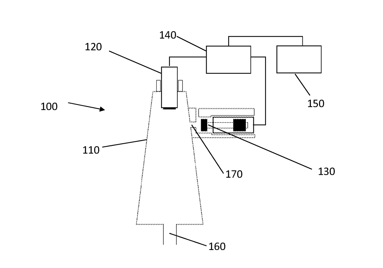
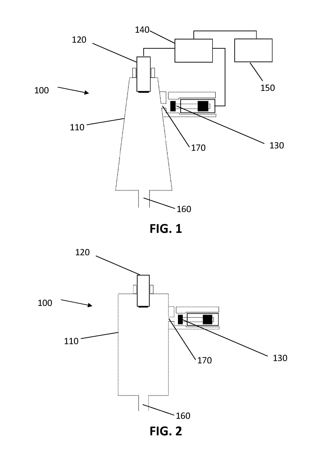
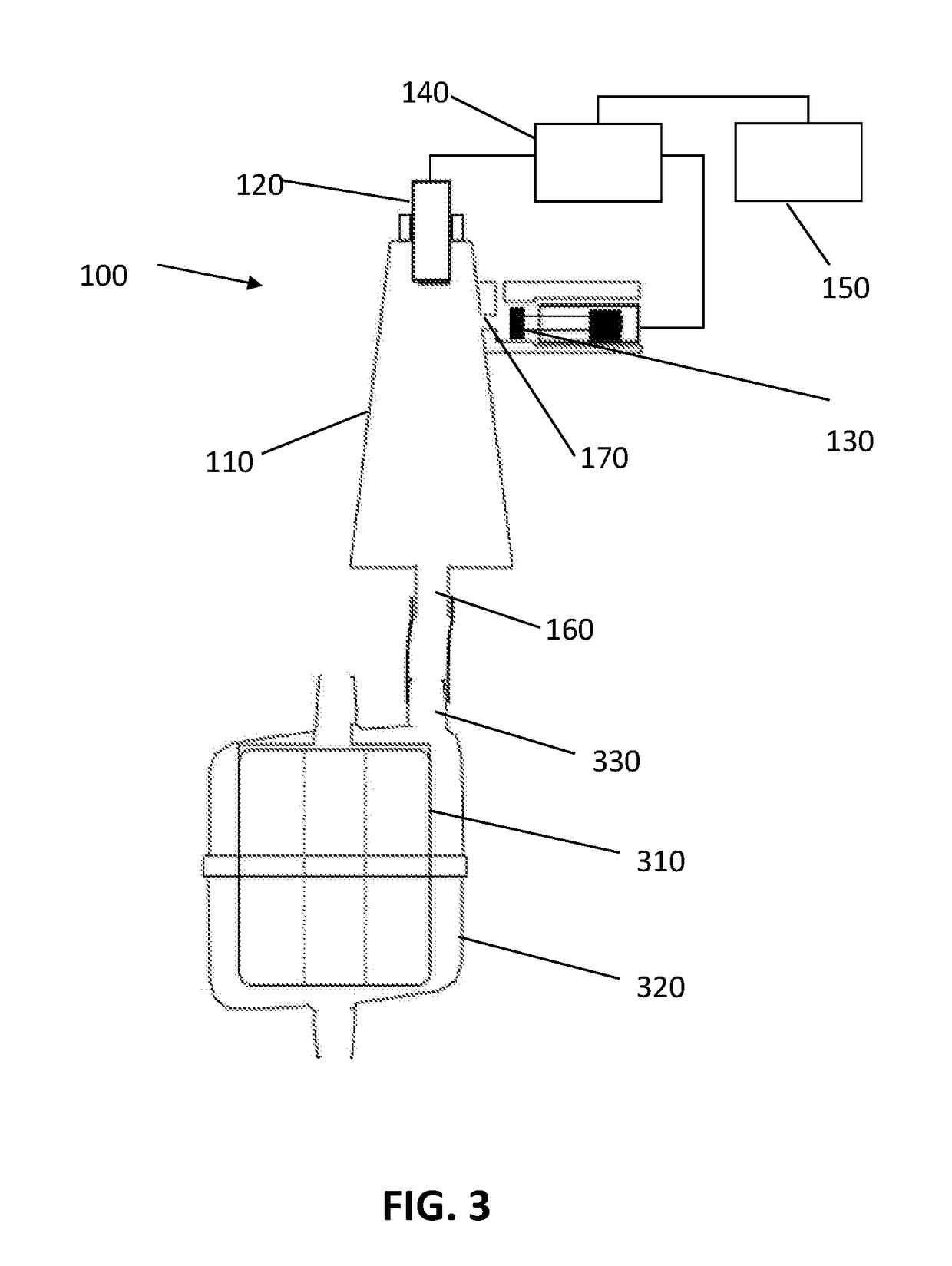
[0044]The present invention will be described in respect of special embodiments and with reference to certain drawings, however the invention will not be restricted to this but will only be restricted by the claims. The drawings described are schematic and not restrictive. In the drawings, the dimensions of some elements have been enlarged and have not been drawn to scale for illustrative purposes. The (relative) dimensions sometimes do not correspond with the embodiment of the invention.

[0045]Furthermore, the terms first, second, third and the like in the description and in the claims are used to distinguish similar elements and are not necessarily used for describing an order, nor in time, nor in space, nor in ranking nor in any other manner. It should be understood that the terms used in this way are interchangeable in appropriate circumstances and that the embodiments of the invention described are suitable to work in a different order than described or indicated here.

[0046]Furt...


PUM

PropertyMeasurementUnit
intrusion pressureaaaaaaaaaa
distancesaaaaaaaaaa
pressureaaaaaaaaaa

Abstract

An air venting device for venting air from a fluid system, the air venting device comprising an air chamber, a sensor and an air venting valve. The sensor can detect a fluid level in the air chamber without coming into contact with the fluid and the air venting valve can be driven on the basis of this sensor measurement.

Description

SCOPE OF THE INVENTION[0001]This invention generally relates to the venting of air from systems which contain a fluid, such as systems in which ink or lacquer is present.BACKGROUND OF THE INVENTION[0002]Fluid systems in which fluids are transported under pressure—such as inkjet printers or filter systems—often encounter the problem that air accumulates somewhere in this system which disturbs the functionality of the system. There are many possibilities of how air can enter into such a fluid system, such as the air can have been trapped in the fluid itself, or the air can also have entered into the fluid system by the opening of the fluid system, or the air can have entered into the fluid system via a pump used for pressurising the fluid. In order to guarantee the proper functioning of the system, it is often important that the accumulated air is removed.[0003]For example, industrial processes adopting filtration techniques often encounter air that accumulates in the filter devices, ...

Claims


Application Information

Patent Timeline
Patent Type & Authority Applications(United States)
IPC IPC(8): B41J2/19B01D36/00
CPCB01D36/001B41J2/19B01D19/0042B01D19/0078B41J2/175
Inventor EURLINGS, MARTIN
Owner ARRANGED
Why Eureka
Try Eureka