Shroud cooling system for shrouds adjacent to airfoils within gas turbine engines

a technology of shrouds and airfoils, which is applied in the direction of engine fuction, leakage prevention, machines/engines, etc., can solve the problems of blade tip clearances that cannot be eliminated, blade tip clearances that can actually decrease, and loss in flow paths, so as to increase cooling efficiency, slow down the thermal response, and enhance cooling

Inactive Publication Date: 2017-06-29
SIEMENS AG
View PDF2 Cites 5 Cited by
  • Summary
  • Abstract
  • Description
  • Claims
  • Application Information

AI Technical Summary

Benefits of technology

[0005]A shroud cooling system configured to cool a shroud adjacent to an airfoil within a gas turbine engine is disclosed. The turbine engine shroud may be formed from shroud segments that include a plurality of cooling air supply channels extending through a forward shroud support for impingement of cooling air onto an outer radial surface of the shroud segment with respect to the inner turbine section of the turbine engine. The channels may extend at various angles to increase cooling efficiency. The backside surface may also include various cooling enhancement components configured to assist in directing, dispersing, concentrating, or distributing cooling air impinged thereon from the channels to provide enhanced cooling at the backside surface. The shroud cooling system may be used to slow down the thermal response by isolating a turbine vane carrier from the cooling fluids while still providing efficient cooling to the shroud.

Problems solved by technology

Turbine engines commonly operate at efficiencies less than the theoretical maximum because, among other things, losses occur in the flow path as hot compressed gas travels down the length of the turbine engine.
Blade tip clearances cannot be eliminated because, during transient conditions such as during engine startup or part load operation, the rotating parts (blades, rotor, and discs) and stationary parts (outer casing, blade rings, and ring segments) thermally expand at different rates.
As a result, blade tip clearances can actually decrease during engine startup until steady state operation is achieved at which point the clearances can increase, thereby reducing the efficiency of the engine.
Because the cooling air is passing through the turbine vane carrier, the turbine vane carrier thermally responds to the cooling air temperature, which results in undesirably large blade tip clearances.

Method used


Image

  • Shroud cooling system for shrouds adjacent to airfoils within gas turbine engines
  • Shroud cooling system for shrouds adjacent to airfoils within gas turbine engines
  • Shroud cooling system for shrouds adjacent to airfoils within gas turbine engines

Examples


Embodiment Construction

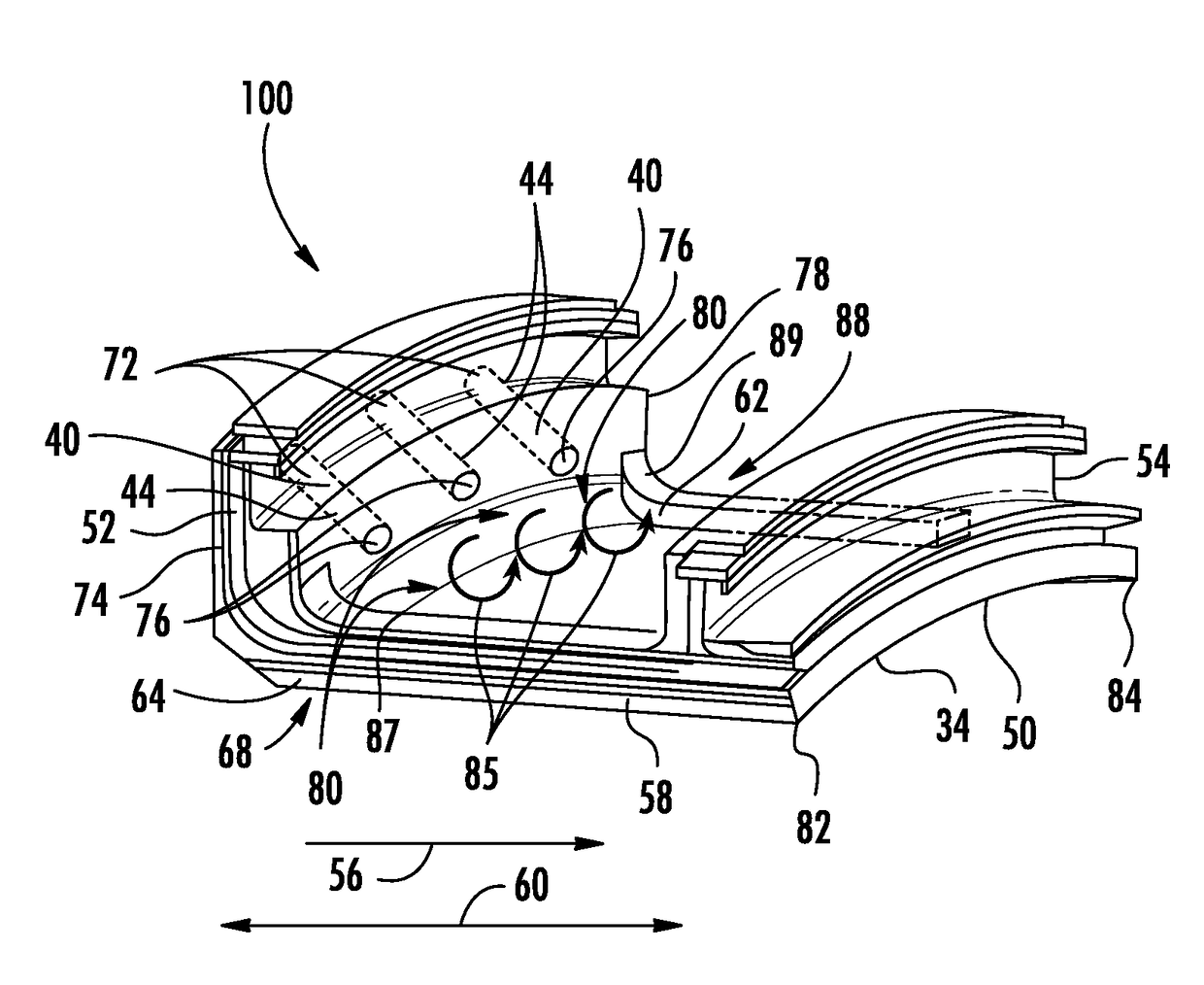
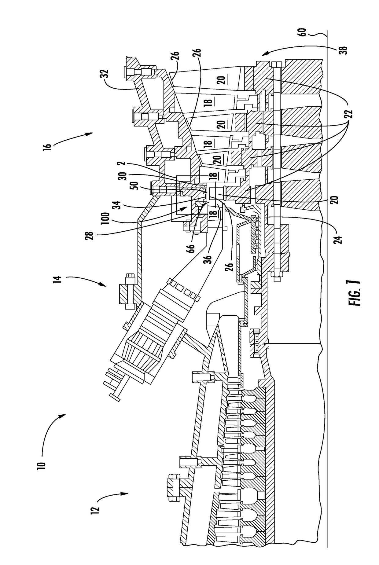
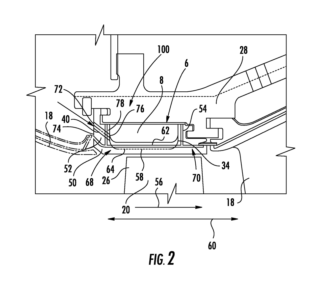
[0014]As shown in FIGS. 1-12, a shroud cooling system 100 configured to cool the shroud 50 adjacent to an airfoil 20 within a gas turbine engine 10 is disclosed. The turbine engine shroud 50 may be formed from shroud segments 34 that include a plurality of cooling air supply channels 40 extending through a forward shroud support 52 for impingement of cooling air onto an outer radial surface 62, commonly called the backside surface 62, of the shroud segment 34 with respect to the inner turbine section 36 of the turbine engine 10. The channels 40 may extend at various angles to increase cooling efficiency. The backside surface 62 may also include various cooling enhancement components 110 configured to assist in directing, dispersing, concentrating, or distributing cooling air impinged thereon from the channels 40 to provide enhanced cooling at the backside surface 62. The present embodiments may be used to slow down the thermal response by isolating a turbine vane carrier 28 from the...


PUM


Abstract

A shroud cooling system (100) configured to cool a shroud (50) adjacent to an airfoil within a gas turbine engine (10) is disclosed. The turbine engine shroud (50) may be formed from shroud segments (34) that include a plurality of cooling air supply channels (40) extending through a forward shroud support (52) for impingement of cooling air onto an outer radial surface of the shroud segment (34) with respect to the inner turbine section of the turbine engine (10). The channels (40) may extend at various angles (42) to increase cooling efficiency. The backside surface (62) may also include various cooling enhancement components configured to assist in directing, dispersing, concentrating, or distributing cooling air impinged thereon from the channels (40) to provide enhanced cooling at the backside surface (62). The shroud cooling system (100) may be used to slow down the thermal response by isolating a turbine vane carrier (28) from the cooling fluids while still providing efficient cooling to the shroud (50).

Description

FIELD OF THE INVENTION[0001]This invention relates generally to gas turbine engines, and more particularly to cooling systems within shrouds adjacent to airfoils in gas turbine engines.BACKGROUND[0002]Turbine engines commonly operate at efficiencies less than the theoretical maximum because, among other things, losses occur in the flow path as hot compressed gas travels down the length of the turbine engine. One example of a flow path loss is the leakage of hot combustion gases across the tips of the turbine blades where work is not exerted on the turbine blade. This leakage occurs across a space between the tips of the rotating turbine blades and the surrounding stationary structure, such as ring segments that form a ring seal. This spacing is often referred to as the blade tip clearance.[0003]Blade tip clearances cannot be eliminated because, during transient conditions such as during engine startup or part load operation, the rotating parts (blades, rotor, and discs) and stationa...

Claims


Application Information

Patent Timeline
Patent Type & Authority Applications(United States)
IPC IPC(8): F01D25/12F01D9/04F01D11/08
CPCF01D25/12F01D11/08F01D9/04F05D2260/232F05D2260/201F05D2260/22141F05D2220/32F01D25/14
Inventor ENG, DARRYLRAWLINGS, CHRISTOPHERPECHETTE, THOMASROGERS, FRIEDRICH T.UM, JAE Y.LEE, CHING-PANG
Owner SIEMENS AG
Why Eureka
Try Eureka