

Cooling circuit for internal combustion engines
a technology for internal combustion engines and cooling circuits, which is applied in the direction of machines/engines, mechanical equipment, transportation and packaging, etc., can solve the problems of excessive temperature of the coolant in the exhaust heat recovery system, excessive heat generation of the coolant, and excessive boiling of the coolan
- Summary
- Abstract
- Description
- Claims
- Application Information
AI Technical Summary
Benefits of technology
Problems solved by technology
Method used
Image

Examples
first embodiment
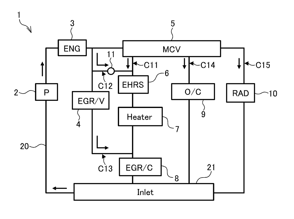
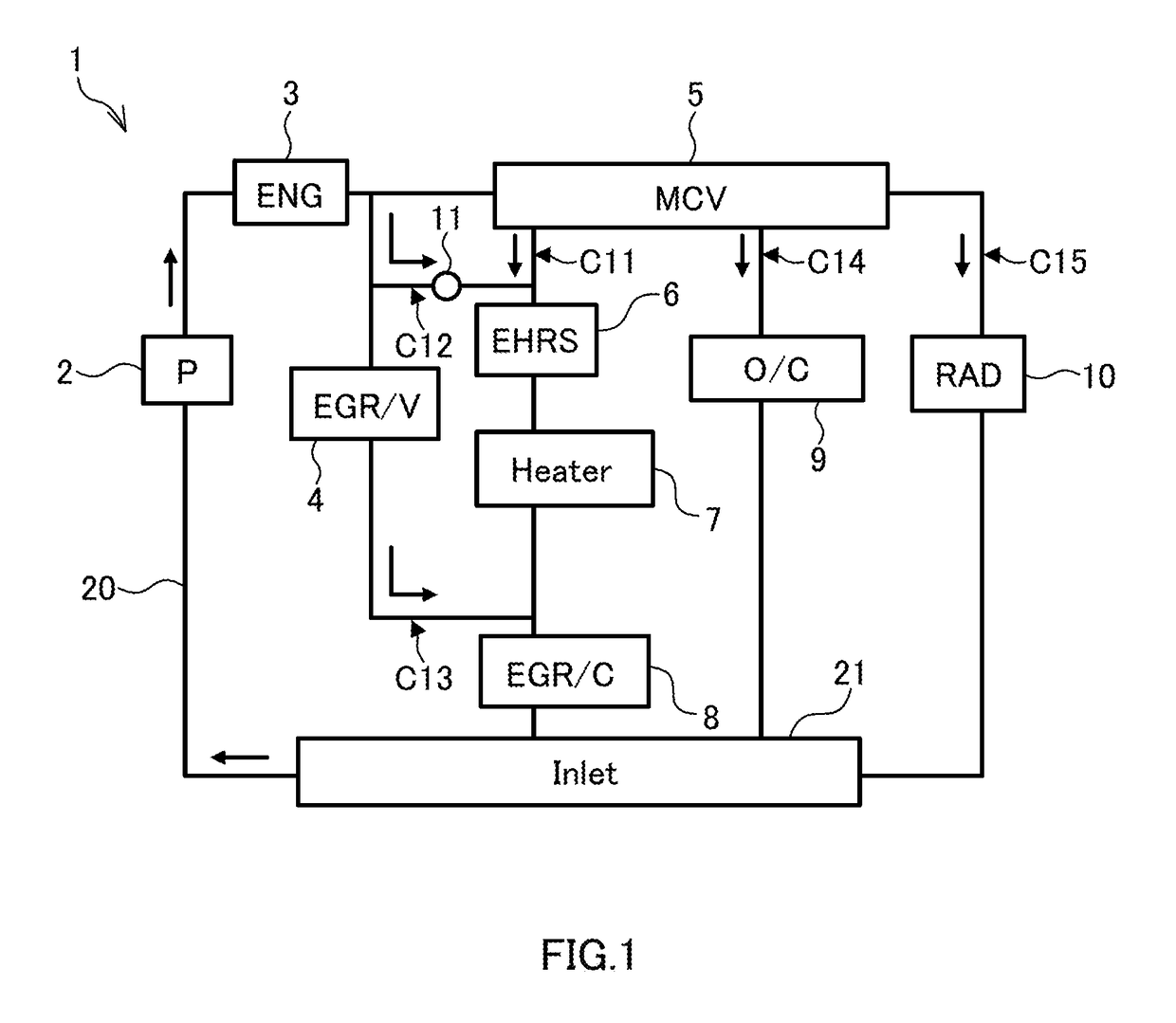
[0018]FIG. 1 is a schematic configuration diagram of a cooling circuit 1 for internal combustion engines according to a first embodiment. The cooling circuit for internal combustion engines is called a cooling circuit below. The cooling circuit 1 includes a pump 2, an internal combustion engine 3, an EGR valve 4, a multi-control valve 5, an exhaust heat recovery system (EHRS) 6, a heater core 7, an EGR cooler 8, an oil cooler 9, a radiator 10, an orifice 11 and connection passages 20. Arrows along the connection passages 20 indicate flows of coolant for cooling the internal combustion engine 3. The cooling circuit 1 circulates the coolant. Antifreeze can be applied as the coolant.
[0019]The pump 2 feeds the coolant under pressure. A mechanical pump driven by power of the internal combustion engine 3 can be applied as the pump 2. The pump 2 includes a coolant inlet 21. The coolant inlet 21 is arranged in a housing of the pump 2. In FIG. 1, the coolant inlet 21 is shown at a position d...
second embodiment
[0060]FIG. 5 is a schematic configuration diagram of a cooling circuit 1 according to a second embodiment. In the present embodiment, connection passages 20 form the following circulation circuits C11 and C12. In the present embodiment, the circulation circuit C12 doubles as the circulation circuit C13. Circulation circuits C14 and C15 are formed as in the first embodiment.
[0061]The circulation circuit C11 circulates coolant through a pump 2, an internal combustion engine 3, an MCV 5, a heater core 7, an exhaust heat recovery system 6 and an EGR cooler 8 in this order. Thus, the heater core 7 is arranged upstream of the exhaust heat recovery system 6 in the circulation circuit C11. Specifically, the heater core 7 is arranged between the MCV 5 and the exhaust heat recovery system 6. The circulation circuit C12 circulates the coolant through the pump 2, the internal combustion engine 3, an EGR valve 4, the exhaust heat recovery system 6 and the EGR cooler 8 in this order.
[0062]The coo...
third embodiment
[0066]FIG. 6 is a schematic configuration diagram of a cooling circuit 1 according to a third embodiment. In the present embodiment, an internal combustion engine 3 includes a coolant outlet 31. In FIG. 6, the coolant outlet 31 is shown at a position distant from the internal combustion engine 3 for the convenience of description. The coolant outlet 31 may not be a part of the internal combustion engine 3. In the present embodiment, a pump 2 includes no coolant inlet 21 for causing the circulation circuits C11, C14 and C15 to join each other. In the present embodiment, an MCV 5 is arranged to be connected to an inlet side of the pump 2. The cooling circuit 1 includes no orifice 11 as in the second embodiment.
[0067]In the present embodiment, connection passages 20 form the following circulation circuits C11, C12, C14 and C15. In the present embodiment, the circulation circuit C12 doubles as the circulation circuit C13.
[0068]The circulation circuit C11 circulates coolant through the p...
PUM
 Abstract
Description
Claims
Application Information