Eye tracker system and methods for detecting eye parameters

a technology of eye tracking and eye parameters, applied in the field of video oculography, can solve the problems of generating megabits of data per second, lack of wearable eye tracking devices, and inability to wear wearable eye tracking devices, and achieves the effects of improving the robustness reducing the cost of power consumption, and improving the reliability of the eye tracking platform

Active Publication Date: 2017-07-06
UNIV OF MASSACHUSETTS
View PDF3 Cites 42 Cited by
  • Summary
  • Abstract
  • Description
  • Claims
  • Application Information

AI Technical Summary

Benefits of technology

[0030]According to the invention, pupil centers may be tracked with accuracy of roughly 1 pixel (0.3°) and pupil dilation with accuracy of approximately 1 pixel (0.22 mm) in indoor lighting conditions. In addition, the invention adjusts to indoor and outdoor illumination using an indoor-outdoor near-infrared (NIR) sensing component with pupil center error increasing only by a modest amount in outdoor settings (4 pixels or 1.2°). Another advantage of the eye tracker according to the invention is that it operates end-to-end at a total power budget of 7.5 mW when running at 4 Hz, which 10× less than that currently known in the art. Alternatively, invention can achieve eye tracking rates of upwards of 250 frames / second by scaling power consumption up to 32 mW.
[0031]In particular, the controller and an IR photodiode detect an outdoor lighting condition. In response, the controller adjusts various camera parameters, such as the gain function, to be better suited to capture images and pixels in the outdoor lighting condition. The controller also hard-codes a previously calibrated model optimized for outdoor lighting conditions. The controller further omits the tracking step and solely relies upon the estimating step to determine the location and size of the pupil. In this way, the controller increases the robustness of the eye tracking platform at a modest cost in power consumption.

Problems solved by technology

Despite the enormous potential for advancing detection of health states and understanding of human decision making by measuring the eye, progress has been stymied by the lack of wearable eye trackers that are integrated into a regular pair of eyeglasses.
The design of a low-power wearable eye tracker is remarkably challenging from the computation, sensing, communication, and aesthetic design perspectives.
A real-time eye tracker involves an eye facing imager sampling at frame rates of tens of Hz (up to 100 Hz to detect fine-grained eye movements or saccades) thereby generating megabits of data per second and making communication to a phone extremely power-hungry.
As a reference point, the Google Glass optical head-mounted display lasts only a few hours when streaming from its outward facing camera, while running too hot for comfort.
Real-time computation on the eyeglass is also remarkably challenging, particularly given the volume of data and complexity of the image processing techniques.
While the focus in is on the computation and power aspects, aesthetic design presents an equally significant challenge since the sensors need to be embedded in an unobtrusive manner within an eyeglass frame.
While many eye trackers are available for commercial use, they are expensive, power hungry and relatively bulky, which makes them less than ideal for regular use.
Several efforts have been made to design low-power wearable eye trackers, but many challenges remain.
Eye trackers simply do not work outdoors given the variability in outdoor lighting conditions.
More generally, achieving robust operation in environments with different illumination conditions is extraordinarily challenging and has not been achieved so far by either research prototypes or bulkier commercial products.
While some eye trackers rely on visible light, they fail under poorly illuminated conditions.
Many commercial eye trackers use near-infrared (NIR) illumination of the eye, but fail to operate effectively outdoors due to overwhelming ambient infrared light.
For example, if air traffic control (ATC) operators become distracted or their performance impaired, thousands of people could be put in danger.
Relying on self-awareness is not sufficient according to experts, both drivers and employees in sensitive positions fail to recognize their fatigue and drowsiness state.

Method used


Image

  • Eye tracker system and methods for detecting eye parameters
  • Eye tracker system and methods for detecting eye parameters
  • Eye tracker system and methods for detecting eye parameters

Examples


Embodiment Construction

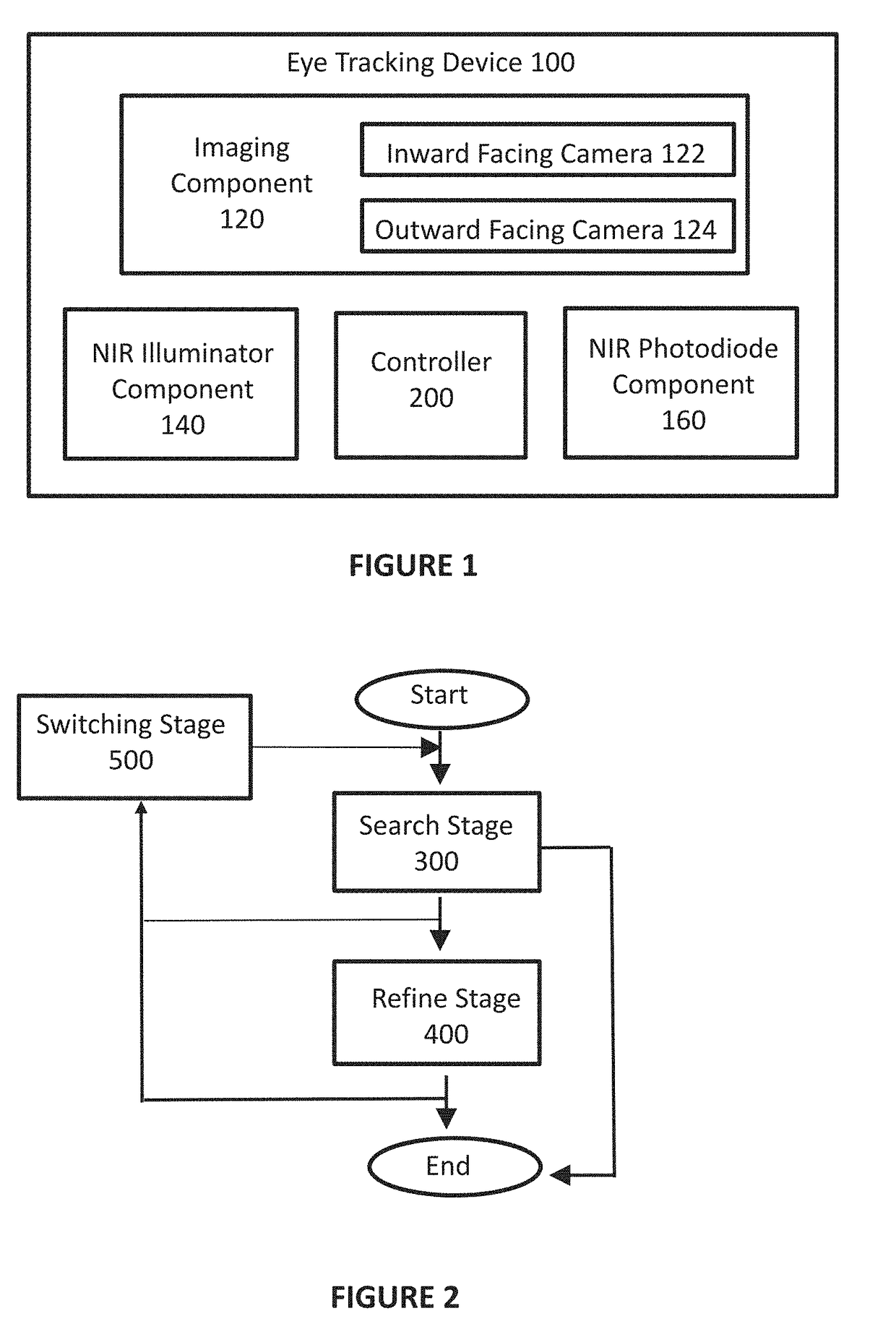
[0057]The invention detects eye parameters using a staged architecture that trades off power for robustness. The architecture uses an optimized detector for the “common case” involving a user being indoors and in limited-noise settings, and tremendously reduces the overall power consumption down to numbers that are within the range of typical wearable devices. Noise and variable illumination settings are dealt with by using more computational and sensing heft to filter out noise and deal with variability. Very high frame rates are achieved providing the ability to sense fine-grained eye parameters. Most surprisingly, all of this functionally is achieved while operating on a small controller such as an ARM Cortex M3.

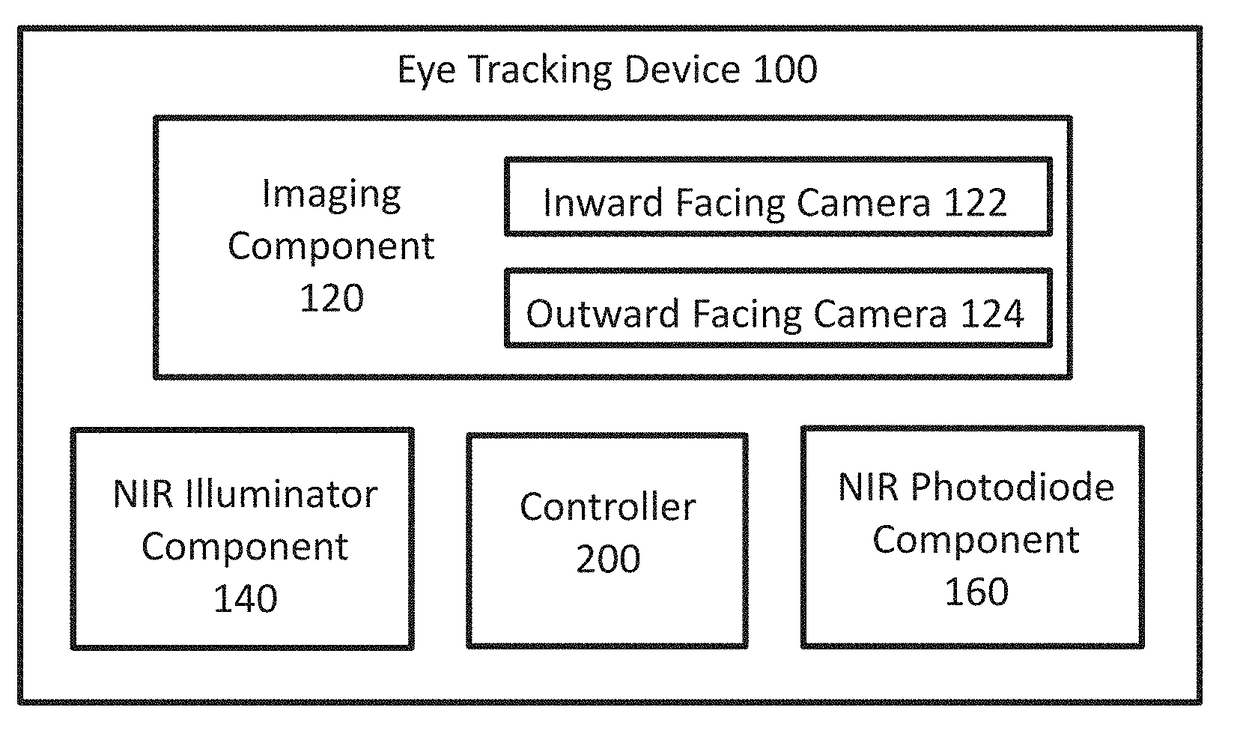
[0058]The eye tracking system for detecting eye parameters illustrated in FIG. 1 is directed to a device 100 such as an eyeglasses. An imaging component 120, such as a camera, is mounted on the device 100. In certain embodiments the imaging component 120 includes an inwar...


PUM


Abstract

An improved eye tracker system and methods for detecting eye parameters including eye movement using a pupil center, pupil diameter (i.e., dilation), blink duration, and blink frequency, which may be used to determine a variety of physiological and psychological conditions. The eye tracker system and methods operates at a ten-fold reduction in power usage as compared to current system and methods. Furthermore, eye tracker system and methods allows for a more optimal use in variable light situations such as in the outdoors and does not require active calibration by the user.

Description

CROSS-REFERENCE TO RELATED APPLICATIONS[0001]This application claims priority to U.S. Provisional Patent Application 62 / 214,512 filed Sep. 4, 2016, incorporated herein by reference.FEDERALLY SPONSORED RESEARCH OR DEVELOPMENT[0002]This invention was made with government support under 1217606, 1218586, and 1239341 awarded by The National Science Foundation and 1U54EB020404 awarded by The National Institutes of Health. The government has certain rights in the invention.FIELD OF THE INVENTION[0003]The invention relates generally to video oculography, i.e., gaze tracking using eye images. More specifically, the invention relates to a highly optimized low-power wearable eye tracker and methods for detecting eye parameters including eye movement, pupil center, pupil diameter (i.e., dilation), blink duration, and blink frequency. These parameters may then be used to determine a variety of physiological and psychological conditions.BACKGROUND OF THE INVENTION[0004]The human eye offers a fasc...

Claims


Application Information

Patent Timeline
Patent Type & Authority Applications(United States)
IPC IPC(8): A61B3/113G02B27/00G02B27/01A61B3/032
CPCA61B3/113A61B3/032G02B27/0093G02B2027/0187A61B3/10G02B2027/0178G02B27/017
Inventor GANESAN, DEEPAKMARLIN, BENJAMIN M.MAYBERRY, ADDISONSALTHOUSE, CHRISTOPHER
Owner UNIV OF MASSACHUSETTS
Why Eureka
Try Eureka