Thin film deposition preparation device and method

a technology of thin film and preparation device, which is applied in the direction of chemical vapor deposition coating, vacuum evaporation coating, coating, etc., can solve the problems of wasting rest of energy by thermal objects, difficult design of high-temperature sources, and complicated to achieve the specific motion of large-size substrates in order, etc., to achieve simple and convenient operation, fast heating, and easy adjustment

Inactive Publication Date: 2017-07-06
UNIV OF ELECTRONICS SCI & TECH OF CHINA
View PDF1 Cites 0 Cited by
  • Summary
  • Abstract
  • Description
  • Claims
  • Application Information

AI Technical Summary

Benefits of technology

[0016]The invention herein also provides a method for preparing thin films, including the following steps: 1) metal substrate heating, 2) thin film deposition. The method is characterized in the step 1) that the current flows into the metal substrate through the electrode beside one end of the growth zone and flows out of the metal substrate through another electrode beside the other end of the growth zone, and the metal substrate is heated by the Joule effect because of the resistant of the metal substrate itself. Noteworthily, the current flows into and out of the metal substrate through its edges.
[0017]Compared to the conventional methods of heating metal substrate, the invention herein is simpler in the principle and configuration, and can be employed to heat either the bare metal tape or the oxide-buffered metal tape no matter whether the oxide buffers are conductive. The invention herein can also achieve the sectional heating of the metal tape no matter whether the metal tape is moving or static. The metal tape can be fast heated to 800° C. or above with applying the invention, and the temperature along the tape is uniform. And this uniform temperature zone can be easily adjusted. The invention herein has high energy efficiency, and can also achieve the continuous and reel-to-reel fabrication of multi-layer thin films. The above-mentioned advantages of the invention herein is especially important to industrial fabrication of thin films, and can improve the quality of the fabricated films, as well as decrease the fabrication cost. Furthermore, the simultaneous and uniform fabrication of double-sided films on both surfaces of the metal tape can also be easily achieved by the invention herein, which is important to improve the use factor of the metal tape and the performance, as well as to decrease the cost.

Problems solved by technology

The other is that it's complicated to achieve the specific motion of the large-size substrate in order to fabricate large-scale uniform thin film; (2) Heating through thermal radiation.
Compared to method (1), the advantage of this method is that the substrate can be free and be of larger size, while the disadvantage is that the high-temperature source is more difficult to design and needs more space; (3) Heating by induction.
During the transferring or transforming process, only a small part of the energy is practically utilized to heat substrate and the rest part of the energy is wasted by the thermal objects or the electric source themselves.
To prepare the thin film on long and thin metal tape, the above heating method (1) is improper because such metal tape is flexible, especially for the moving metal tape.
Generally, the design is complicated.
Consequently, the temperature can't be accurately controlled under the simultaneous action of the induction heating and the plasma.
Furthermore, the heating manner in US 20140033976A1 is also inconvenient to simultaneously deposit thin films on both faces of the metal tape substrate.

Method used


Image

  • Thin film deposition preparation device and method
  • Thin film deposition preparation device and method
  • Thin film deposition preparation device and method

Examples


embodiment 1

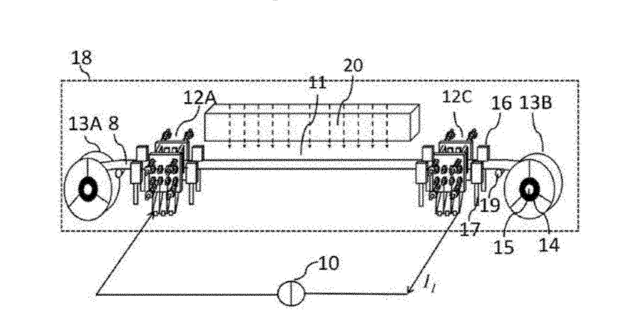
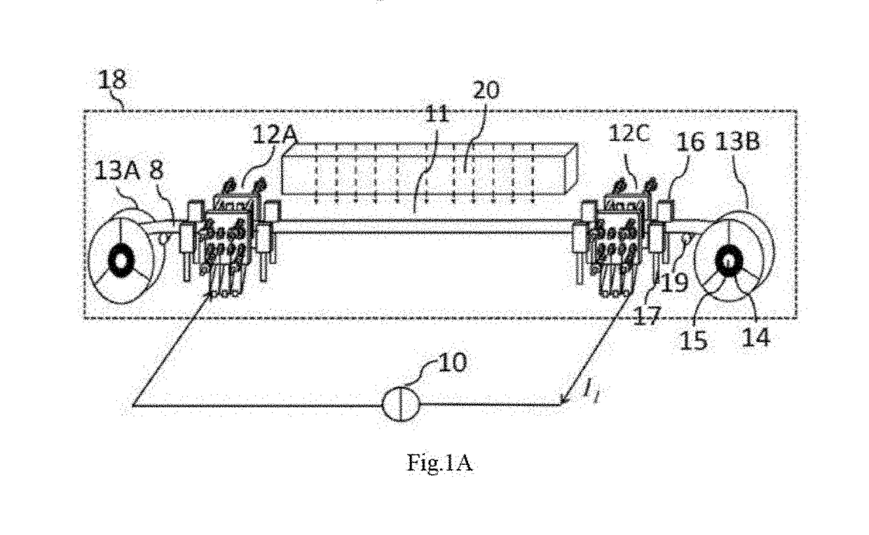
[0045]As what is shown in FIG. 1, the embodiment 1 comprises a growth chamber 18, two rotation shafts 15 of substrate rolls and substrate-heating setup. The substrate-heating setup herein consists of the first electrode configuration 12A and the second configuration 12C, which are settled side by side between the rolls 13A and 13B in the growth chamber 18; and the rolls 13A and 13B are installed by the two rotation shafts 15; the thin film growth zone 11 is located between the two electrode configurations, 12A and 12C.

[0046]The electrode configurations, 12A and 12C, are same with each other.

The first electrode configuration 12A consists of an interface to current source 10 and at least two conductive metal strips 2, which are distributed along two sides of the substrate passage and electrically connected with each other as well as the current source 10. The first electrode configuration 12A is installed in growth chamber 18 through the first settlement configuration.

[0047]The first ...

embodiment 2

[0051]As what is shown in FIG. 2, at wording state the substrate-heating setups and metal tape 8 are settled by referring to the embodiment 1. However, there is difference that there are deposition sources over both faces of the metal tape 8 in the growth zone 11 in the embodiment 2, therefore simultaneous deposition of double-sided thin films on both faces of metal tape 8 can be achieved. With the assistance of the movement of metal tape 8, the continuous and reel-to-reel deposition of double-sided thin films on metal tape 8 can be realized.

embodiment 3

[0052]As what is shown in FIG. 3, at wording state the substrate-heating setups and metal tape 8 are settled by referring to the embodiment 1. However, the difference between embodiment 1 and 3 is that one extra electrode configuration 12B is installed between the two electrode configurations, 12A and 12C, therefore there are two growth zones, 11A and 11B, in which there are four deposition sources 20A, 20B, 20C and 20D over both faces of the metal tape 8. The first electrode configuration 12A is connected to the anodes (or cathodes) of the current source 9 and 10, and the extra electrode configuration 12B and the second electrode configuration 12C are connected to the cathodes (or anodes) of current source 9 and 10, respectively. The heating current I1 and I2 flow from the anodes of current sources 9 and 10 to the first electrode configuration 12A, and then converged into metal tape 8. The converged I1+I2 will transmit only in the part of metal tape 8 located in the growth zone 11A...


PUM

PropertyMeasurementUnit
temperatureaaaaaaaaaa
weightaaaaaaaaaa

Abstract

The invention provides a thin film deposition system and a method, and relates to the field of thin film deposition. The deposition method comprises the following steps: 1) heating metal substrate; carrying out deposition. The method is characterized in the step 1) that a current is conducted into the metal substrate at one end of the growth zone by one electrode, and out of the metal substrate at the other end of the growth zone by the other electrode, so that the metal substrate is heated by the heat emitting of the resistant of the metal substrate itself. According to the method, the quality of the prepared thin film is improved, while the preparation cost of the thin film is reduced. In addition, the consistent double-sided thin films can be easily prepared on two surfaces of the metal substrate by employing the system and method.

Description

FIELD OF THE INVENTION[0001]The invention relates to the fabrication of thin films, especially those on the static or moving long metal tape substrates.BACKGROUND OF THE INVENTION[0002]In the field of thin film fabrication, the substrate generally needs to be heated to control the growth of the thin film, thereby adjust the physical and chemical properties of the film. The conventional heating methods are as the followings: (1) Heating through thermal conduction. Namely, the substrate is pasted to a thermal source and the heat is directly transferred from the thermal source to the substrate. This heating method requires that the substrate is closely contacted to the thermal source to assure the uniform and consistent conduction of the heat. Consequently, there are two shortcomings of this heating method. One is that the size of the substrate can't be too large in order to avoid the inhomogeneous heating resulting from the poor contact between substrate and thermal source. The other ...

Claims


Application Information

Patent Timeline
Patent Type & Authority Applications(United States)
IPC IPC(8): C23C16/46C23C16/56C23C14/24
CPCC23C16/46C23C16/56C23C14/24C23C14/08C23C14/541C23C14/562C23C16/40C23C16/545
Inventor TAO, BOWANXIONG, JIEZHANG, FEILI, CHAORENZHAO, XIAOHUILI, YANRONG
Owner UNIV OF ELECTRONICS SCI & TECH OF CHINA
Why Eureka
Try Eureka